
Grader Blade Bolt Patterns and Hole Spacing: The Layout Checklist
A bolt pattern is the part of an edge order that cannot be corrected after delivery. Grade can be changed on the next order, thickness can be argued about, but a pattern that does…
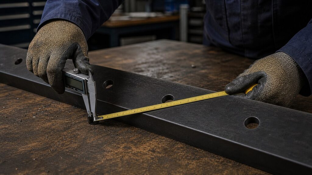
A bolt pattern is the part of an edge order that cannot be corrected after delivery. Grade can be changed on the next order, thickness can be argued about, but a pattern that does not match the moldboard turns the edge into scrap or an expensive re-machining job. This checklist covers what to measure, how to record it, and how to verify a delivery before it goes onto a machine.
What the Machine Determines and What the Edge Determines
The split of responsibility is simple and worth stating before any measurement is taken. The machine determines the pattern: hole positions are fixed by the moldboard, and the edge has to reproduce them. The edge determines everything that bolts through those holes — its own thickness at the hole line, the countersink that receives the fastener, and the section profile that has to sit against the moldboard’s lip.
That split matters because it defines what a supplier can be asked to hold and what has to be supplied as input. A manufacturer can hold a pattern to a stated tolerance; it cannot determine what the moldboard’s pattern is without data. Every fitment failure in this product category is, in the end, a failure to get that data across the boundary.
Two categories of information therefore travel with an order: the pattern, which comes from the machine or a drawing, and the product specification, which comes from the buyer’s requirement and the supplier’s capability. Keeping them in separate sections of the same document removes most of the ambiguity that causes rework.
The Measurements to Take in the Shop
A pattern can be captured in the workshop in under an hour, with a tape, a set of callipers and a clean edge. Six numbers matter.
- Overall length of the edge and the position of the first and last holes relative to the ends.
- Hole diameter, measured on a clean, unworn hole rather than on an elongated one.
- Hole spacing centre to centre, recorded as a running sequence rather than as an average interval, because some patterns are not evenly divided.
- Hole-centre-to-edge distance, from the hole line to the cutting edge.
- Countersink angle and head diameter if the fastener is countersunk, since this is what the bolt head seats in.
- Section profile and thickness, taken at the seating face rather than at a worn portion of the edge.
Photograph the layout with a tape in frame and sketch the hole sequence. A sketch with numbers is considerably more useful to a manufacturer than a photograph alone, because it removes the estimate from the reading. Machine interface conventions that many of these layouts follow are documented in the standards published by SAE.
Tolerance Stack-Up and Elongated Holes
Every dimension in the assembly carries a tolerance: the hole position on the moldboard, the hole position on the edge, the hole diameter, the bolt diameter, and the amount the edge can move before the fastener preload is lost. Fitment problems appear when those tolerances accumulate in the same direction across the pattern.
Elongated holes make the analysis worse in a way that is easy to overlook. A worn hole gives a new edge room to shift under load, which increases movement, which wears the hole further. Once a moldboard has two or three elongated holes, the pattern is no longer the pattern it was built to, and an edge made accurately to the original drawing will still not clamp properly.
The practical responses are to measure holes in their worst condition rather than a favourable one, and to state a tolerance on the order so that receiving inspection has a reference. SENTHAI works to ±0.02 mm on machined features and verifies the pattern against a drawing or a physical sample before production, which is the point at which a stack-up problem should be caught. Where a moldboard is already out of tolerance, machining the edge to fit the worn pattern is usually a better commercial decision than replacing the moldboard, provided the pattern is measured rather than assumed. Material and inspection standards that may be cited in the order come from ASTM and the AASHTO publications programme.
Common Layout Conventions by Machine Class
Patterns are not universal, but they follow weight classes, and knowing the convention for a class is what allows a buyer to sanity-check a quotation before ordering. The machine-side conventions that many patterns follow are published by AEM, and the research literature on road maintenance practice is held by the Transportation Research Board and the DIN standards index is the reference point where a European standard is specified.
| Machine class | Typical pattern character | What to check |
|---|---|---|
| Small utility graders | Fewer, closer-spaced holes in a lighter section | Section thickness and edge length tolerance |
| Mid-size road graders | Repeated evenly spaced pattern, larger fasteners | Countersink match and hole-centre-to-edge distance |
| Heavy grading and mining support | Heavier section, extended patterns, larger bolt sizes | Moldboard lip condition and end bit protection |
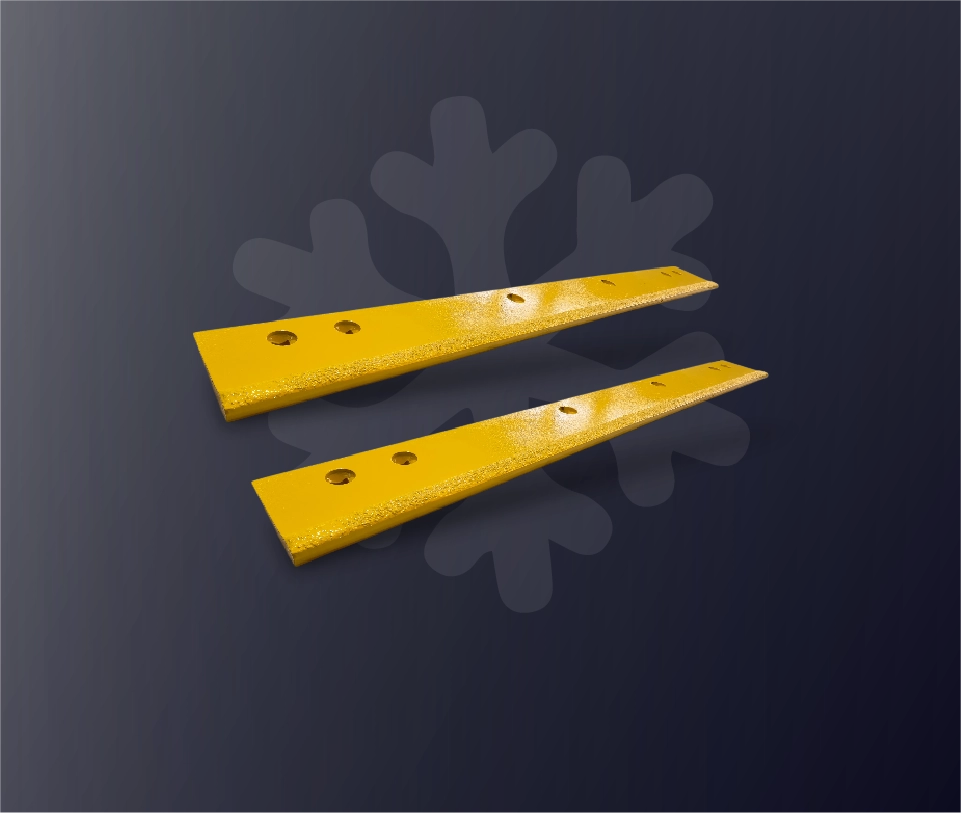
| Wing and specialist edges | Pattern driven by the attachment rather than the moldboard | Attachment drawing is mandatory; measurement alone is not enough |
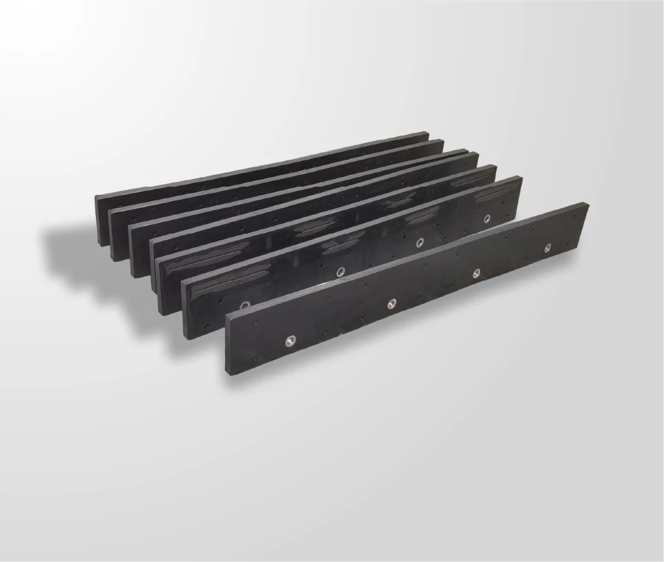
The convention also interacts with the edge profile. A beveled edge presents its fasteners differently from a flat edge, and a curved edge changes where the hole line sits relative to the seating face. That is why a pattern should be recorded together with the section profile rather than as a standalone layout: the two are quoted as one specification, and they are verified as one delivery.
Two conventions are worth flagging because they cause repeated errors. First, hole spacing is often specified as a running sequence rather than a uniform pitch, so an “average” interval will not reproduce the pattern. Second, heavy-edge patterns frequently include a larger hole or a different fastener at the ends, where load concentration is highest.
Verifying a Delivered Edge Against the Drawing
Verification at goods-in is quick and prevents the worst outcome, which is discovering a pattern problem when the machine is standing in the yard. Check the pattern reference on the packing documentation against the order, lay the edge against the moldboard if the machine is available, and measure the hole sequence against the drawing before the edge is released to the workshop.
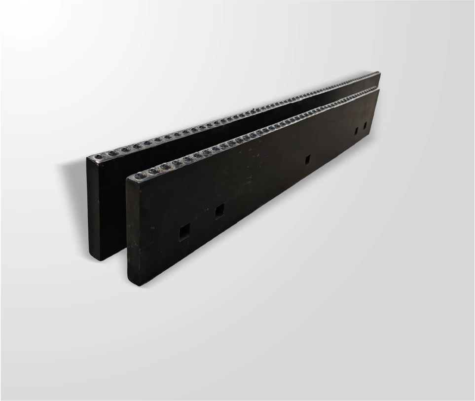
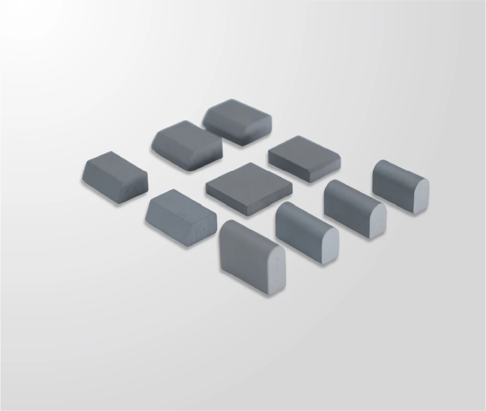
A delivery inspection that covers dimensions, hole pattern, countersink, section profile and surface condition takes minutes per edge. The same discipline applies to a carbide-tipped edge, where the additional check is the condition of the inserts and of the braze line: inserts should be seated flush and evenly spaced, with no visible voids or displacement.
Where a delivery is found to be out of tolerance, record the measurement before contacting the supplier. A measured discrepancy is a conversation with a resolution; a verbal description of a problem is not. Fitment verification against a drawing or physical sample is a documented step at SENTHAI precisely because it is cheaper to correct a pattern before shipment than to resolve a fitment claim afterwards. Public agency programmes typically expect that documentation trail, and the material and testing references that underpin it are published by AASHTO and ASTM.
Fitment Errors and Their Cost
The cost of a fitment error is not the value of the edge. It is the edge, plus the freight both ways, plus the shop time spent discovering the problem, plus the machine hours lost while a replacement is produced and shipped. On a seasonal programme those hours are not recoverable at any price.
Three error types account for most of it. A pattern captured from a worn moldboard reproduces the wear. A pattern captured from a machine label rather than the machine itself assumes a standard that may not apply. And a pattern supplied without the countersink and fastener details produces an edge that fits the holes and will not clamp the bolt heads properly.
Each has the same fix: measure the physical machine, record the numbers with a sketch, and state the full layout on the order including the fastening details. If a fleet manages this once per moldboard variant and keeps the record, the exercise is not repeated.
Recording Fitment for Reorders
The value of measurement work is realised at the next order, and only if it is recorded in a form someone else can use. A fitment record per machine group should hold the moldboard identifier, the hole layout sketch with dimensions, the section profile and thickness, the fastener and countersink, the drawing or pattern reference used by the supplier, and the date of the last verification.
Two fields are worth adding after the first delivery. The as-received measurements, which show whether the supplier held the tolerance, and the machine hours to replacement, which shows whether the section and grade chosen were right for the duty. Together they turn a one-off fitment exercise into a specification that improves each season, and they give a fleet a defensible basis for the next order. The compatibility guide shows the same logic applied to flexible-edge blade systems. The wider range of parts this applies to is covered in wear parts beyond plows.
Pattern data is the one input a supplier cannot generate. Measure the moldboard physically, record the layout as a numbered sketch, state the countersink and fastener alongside it, and put a tolerance on the order. Then verify the first delivery against the drawing and keep the numbers for the next order. Done once per machine group, that routine removes the most expensive failure mode available to a fleet: an edge that cannot be fitted when the season has already started.
Send SENTHAI a hole layout sketch, the section profile and the machine class, and the technical team will confirm the pattern against a drawing or sample and quote it with the countersink and fastener details already matched.
Frequently Asked Questions
How do I measure grader blade bolt holes accurately?
Measure on a clean, unworn hole rather than the worst one on the pattern, then record the spacing as a running sequence rather than an average interval. Take the diameter with callipers, the spacing centre to centre, and the hole-centre-to-edge distance. Sketch the layout with the numbers and photograph it with a tape in frame so the supplier has no figure to estimate.
What happens if the bolt holes on my moldboard are elongated?
An elongated hole lets the edge move under load, which wears the hole further once a new edge is fitted. Measure the holes in their worn condition and tell the supplier, because the edge may need to be made to the actual measured pattern rather than to the original drawing. Where several holes are badly worn, repairing or replacing the moldboard is the more durable fix.
Is hole spacing the same across all motor grader models?
No, spacing follows machine class and moldboard design rather than one universal figure, and some patterns are not evenly divided at all. That is why pattern data has to come from the machine or a drawing. Treat any published chart as a guide for a conversation, and confirm the layout against the physical moldboard before releasing an order.
What tolerance should a grader edge pattern be held to?
Ask for the tolerance to be stated on the quotation so receiving inspection has a reference. SENTHAI works to ±0.02 mm on machined features and verifies the pattern against a drawing or physical sample before production. Without a stated tolerance, a fitment dispute has no baseline and resolution depends on goodwill rather than measurement.
Related articles
Measuring Grader Edge Wear: Replacement Triggers by Machine ClassGrader blades and road grading cutting edges Grader Snow Wings: Mounting, Edge Load and Blade ChoiceGrader blades and road grading cutting edges
 Scarifier Teeth and Shanks: Specifying for Hardpack and GravelGrader blades and road grading cutting edges
 Serrated Versus Straight Grader Edges: When Serration PaysGrader blades and road grading cutting edges