
Geometry and Mounting Structure
Published Wear Component
Groove or Surface Arrangement
Confirm the Actual Process
The construction statements below are taken from SENTHAI’s official carbide snow plow blade information. They describe the product family and are not a universal order specification.
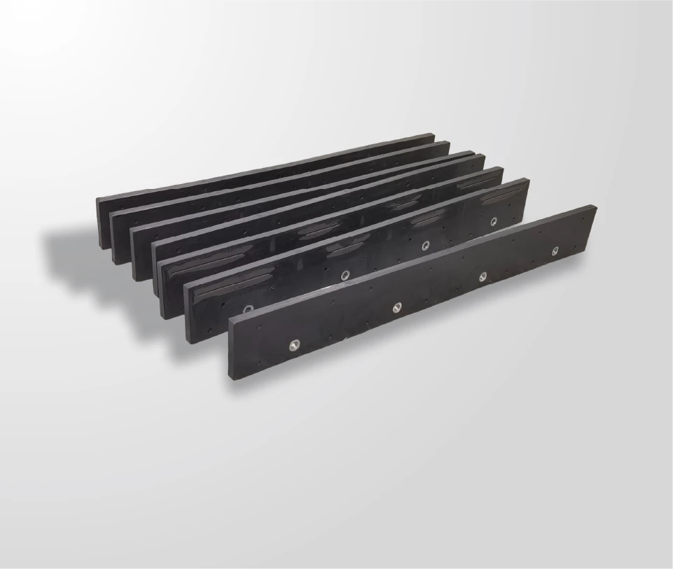
The product page describes its standard as a flat, 3/4-inch-thick metal blade with a single carbide insert brazed onto the face.
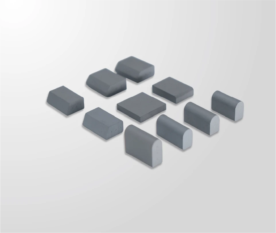
SENTHAI identifies micro-grain tungsten carbide and premium C45 steel for its carbide snow plow blade product family.
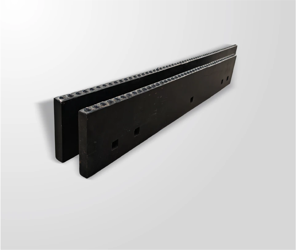
The official product page describes tungsten carbide inserts brazed into milled grooves in the steel blade.
The same official description also refers to carbide inserts overlaid on the blade surface. The selected arrangement must be confirmed.
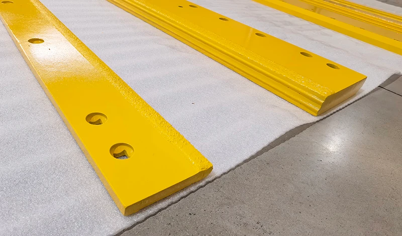
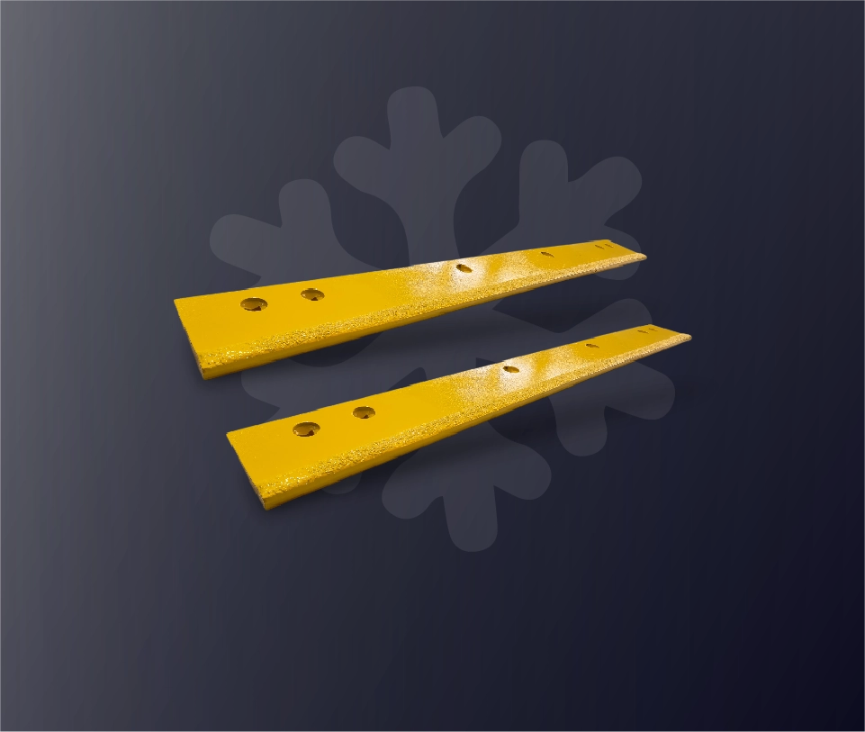
The steel component carries the blade geometry, mounting pattern and the physical interface used with the carbide component. A full product photograph helps identify the general form, but it cannot confirm material grade or hidden dimensions.
✓ Record overall length, height and thickness
✓ Record every mounting hole, slot and reference dimension
✓ Identify bevels, steps, relieved ends and backing components
✓ Mark the installed orientation and road-facing edge
✓ Confirm whether the requested blade follows a standard or custom drawing
The published C45 steel reference should not be copied into an order specification without confirming that it applies to the requested configuration.
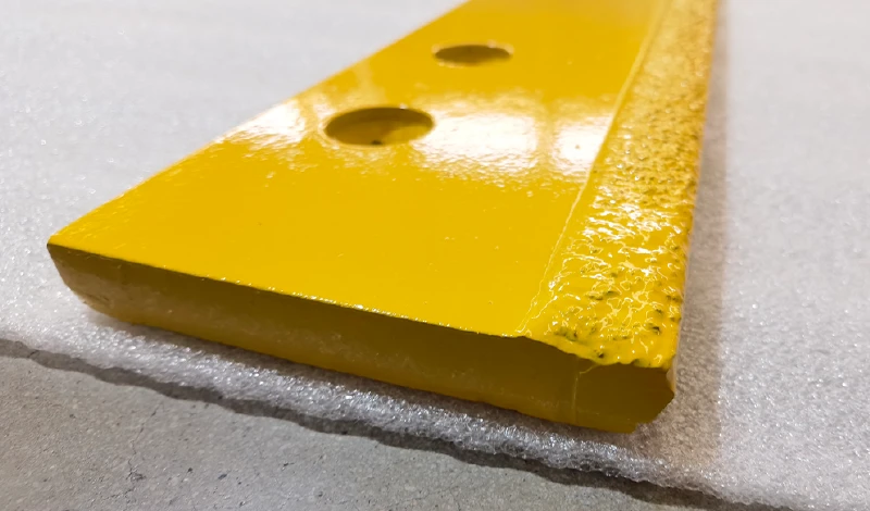
Terms such as groove, face-mounted insert and surface overlay describe different visible arrangements. A buyer should identify which arrangement is required instead of referring only to a generic “carbide blade.”
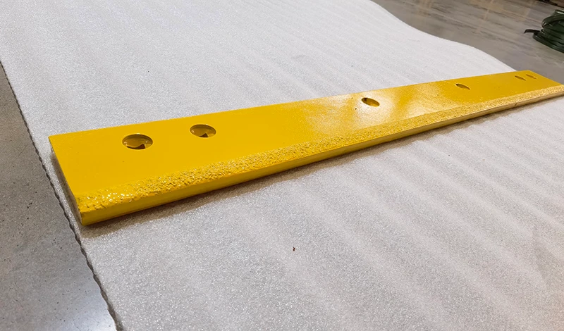
✓ Show the complete carbide line from both faces
✓ Record whether the layout appears continuous or segmented
✓ Photograph the interface at both blade ends
✓ Identify the insert position relative to the mounting holes
✓ Note any groove, step, overlay or backing feature visible in the sample
A photograph does not confirm braze alloy, joining parameters, hidden groove dimensions or acceptance criteria. Those details require an approved product specification.
This structure keeps a general product name from hiding the technical information needed for review.
State the overall geometry, steel requirement if approved, mounting position and hole pattern.
Identify the insert or carbide feature, its position, visible layout and the drawing reference used to define it.
Describe the visible groove, face or surface arrangement without guessing hidden geometry from a photograph.
Define which approved drawing, sample, dimensions and inspection requirements control the final item.
The carbide product page uses the term “brazed” for insert attachment. SENTHAI’s About page separately describes automated induction joining and a subsequent annealing process in its welding hall.
Those published descriptions establish manufacturing capability, but they do not automatically define the process route for every blade configuration.
✓ Confirm which joining description applies to the requested blade
✓ Confirm the approved drawing and process specification
✓ Define visual or dimensional acceptance requirements
✓ Request order-specific records only when required
✓ Avoid inventing braze alloy, temperature or tolerance values
The correct answers depend on the actual application, drawing and commercial requirement.
✓ Which blade family is required?
✓ What mounting position is used?
✓ Is there an approved drawing or sample?
✓ Which dimensions control fit?
✓ Where is the carbide component located?
✓ Is the visible arrangement grooved or overlaid?
✓ Which face and edge define orientation?
✓ What evidence confirms the layout?
✓ What quantity and destination apply?
✓ Are samples or inspection records required?
✓ What packaging and labeling are needed?
✓ Which acceptance criteria are approved?
This protects the page from turning a general product description into an inaccurate universal specification.
✓ Micro-grain tungsten carbide and C45 steel are identified
✓ A flat 3/4-inch-thick standard description is published
✓ Brazed inserts in milled grooves are described
✓ Surface-overlay arrangements are also described
✓ Various sizes and custom blades are stated as available
✓ Exact steel and carbide grades
✓ Insert dimensions and layout
✓ Groove or overlay geometry
✓ Joining materials and process parameters
✓ Tolerances, inspection method and acceptance limits
Each anchor below describes the exact page it opens.
Review SENTHAI’s published carbide snow plow blade materials and construction description.
Record mounting position, geometry, hole pattern and application information for review.
Review how product requirements and order-specific quality records should be separated.
These answers distinguish official product-family descriptions from values that require order-specific confirmation.
The official carbide blade page identifies micro-grain tungsten carbide and premium C45 steel. Confirm that the published material description applies to the specific blade being quoted or approved.
No such universal conclusion should be made. The official page describes inserts brazed into milled grooves and also refers to inserts overlaid on the surface. The actual construction must be defined by the approved requirement.
The product page describes that form as its standard while also stating that varied sizes and custom blades are available. Do not apply the standard description to every custom configuration.
No. A photograph can document visible geometry and condition, but it cannot reliably confirm material grade, hidden groove dimensions, joining material, process parameters or tolerance.
Provide the approved drawing or a measured sample reference, clear photographs, mounting position, blade dimensions, carbide layout, estimated quantity, destination and any required inspection, packaging or labeling information.
Tell us which blade construction you need reviewed. Include the mounting position, drawing or sample information, steel body dimensions, carbide arrangement, estimated quantity and delivery destination.
✓ Product-specific technical review
✓ Standard and custom configurations can be discussed
✓ Drawing and sample references supported
✓ Commercial details reviewed after the construction is defined