
Grader Blade Thickness, Hole Pattern and Bolt Grades
Motor grader blade thickness, hole pattern and bolt grade are the three dimensions that decide whether an edge order is usable: how much material the edge has to wear away, how it bolts to…

Motor grader blade thickness, hole pattern and bolt grade are the three dimensions that decide whether an edge order is usable: how much material the edge has to wear away, how it bolts to the moldboard, and whether it stays clamped. Thickness sets wear life and load capacity, the pattern decides whether the edge bolts to the moldboard, and the bolt grade decides whether it stays clamped. Errors in any of the three produce the same outcome — an edge on the shop floor that cannot be fitted, at the point in the season when it is needed most.
The short version for a buyer writing the order: specify thickness by machine class and duty, specify the pattern from a drawing or a measured moldboard, and specify the fastener by grade and torque with the countersink that matches it.
The Dimensions That Must Match First
Four measurement groups carry the whole fitment decision, and none of them can be inferred from a machine’s model year. They are the hole diameter, the hole spacing along the pattern, the distance from the hole centre to the cutting edge, and the section profile that has to follow the moldboard’s arc.
Thickness is the fifth dimension and the one most often bought by habit. It has to match the machine class and the load the edge will carry, and it has to be consistent across the order: a delivery that mixes sections within one part number creates a fitment problem that no drawing review will catch.
The reason to fix these first is that they constrain everything else. Once pattern and thickness are settled, the grade, the profile and the price follow; while they are open, every quotation being compared is describing a different product.
Thickness Versus Wear Life and Weight
Thickness is wear allowance as much as it is strength. A heavier section simply has more material to lose before the edge stops cutting and the tip becomes too round to grade effectively, so heavier edges last longer in service — and they cost more, weigh more, and load the machine’s moldboard and lift system more heavily.
There is a point beyond which extra thickness stops paying. The moldboard’s lower lip takes the bending load, and an edge that is significantly heavier than the section it seats against shifts stress to the plate rather than absorbing it. Fleets that step up a section size without checking the moldboard often find the edge survives while the seating face distorts.
Duty matters as much as class here. A grader working crushed surfacing in a mountain district consumes section far faster than one dressing soft shoulders on a coastal plain, and the same machine may need two different thicknesses if it moves between those programmes. Where a fleet cannot standardise on one section, recording wear per route is what justifies the split.
The other half of the trade-off is handling. Edges are physical objects with real mass, and a heavier section changes the change-out job itself: more lifting, more care with alignment, more consequence if the fasteners are not correctly torqued. Where a fleet changes edges in the field rather than in a shop, that operational burden belongs in the decision.
Hole Pattern and Bolt Size Conventions
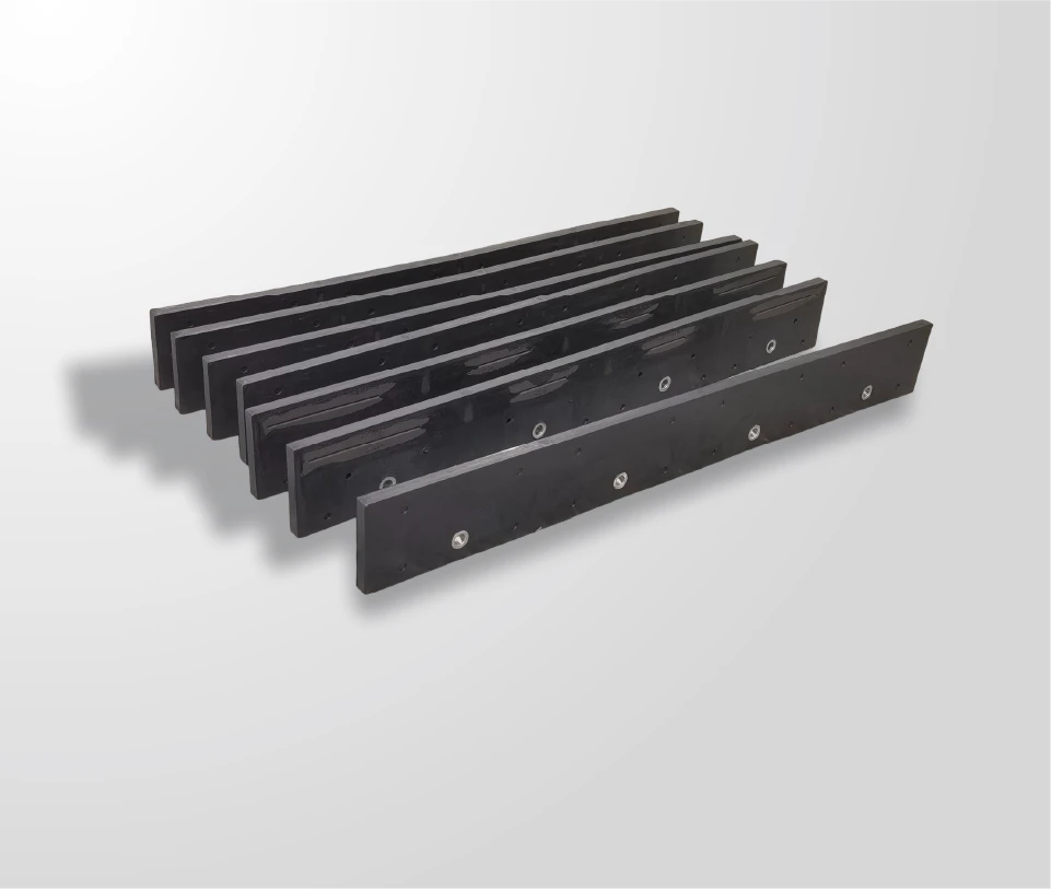
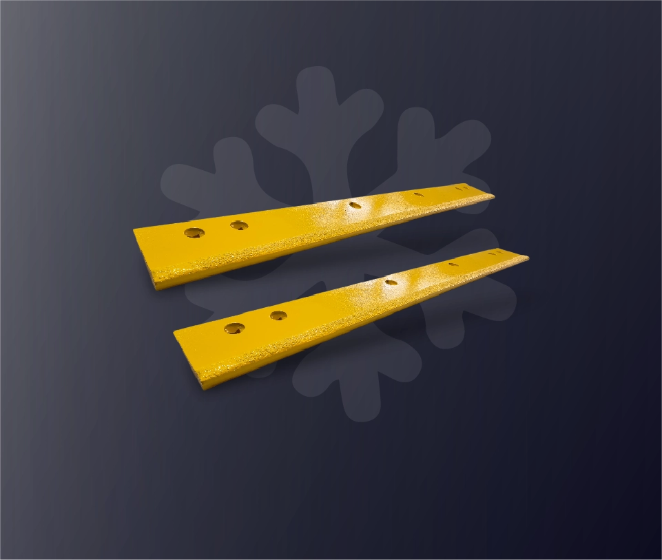
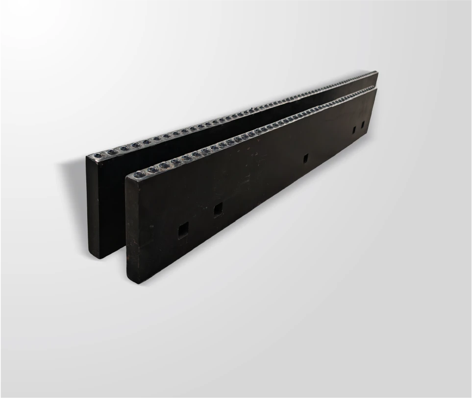
Hole pattern is not a universal standard, which is why the machine class and the moldboard matter more than the brand. Within a class, however, conventions are consistent enough that an experienced buyer can predict the general layout: a repeated pattern of countersunk holes spaced along the edge, sized for the plow bolts used at that weight of machine.
Two details are commonly mishandled. The first is the bolt size, which must match both the hole diameter and the countersink: an over-sized hole with an under-sized bolt will not clamp, and a mismatched countersink leaves the head proud so that it wears and loses torque. The second is the relationship between the hole line and the cutting edge, which sets how much material remains at the bolt line when the edge is at the end of its life.
Where a fleet runs mixed equipment, the practical approach is a pattern library: one drawing per moldboard variant, referenced on every order. Machine interface conventions that sit behind many of these layouts are published by SAE, and the material and inspection standards a public agency may reference come from ASTM and the AASHTO publications programme. Where a European standard is required in the specification, the relevant index is held by DIN.
Bolt Grade and Torque Requirements
Bolts are the cheapest component in the assembly and the most common cause of an edge coming loose. The grade has to suit the load, and the torque has to suit the grade: an under-torqued edge moves, wears the holes oval and eventually cracks, while an over-torqued fastener stretches and loses preload within the first hours of work.
Practically, three rules hold. Replace fasteners whenever the edge is changed, because a used plow bolt has already yielded. Confirm that the countersink accepts the bolt head flush. And work to a torque value taken from the machine or fastener specification rather than from habit, because the correct value depends on bolt size, grade and the material being clamped.
Re-torquing after the first shift is worth building into the change-out routine. New edges seat slightly under load, preload drops, and the first re-check catches the cases that would otherwise become a loose edge by the second week. Fastener test and grade standards are published by ASTM, and equipment manufacturers’ industry material from AEM covers the machine-side conventions that torque values are written against.
Checking the Moldboard Before Ordering
Ordering to a measured moldboard is cheaper than ordering to a remembered specification, and the check takes shop time rather than engineering time. Four conditions are worth verifying before the order is released.
- Hole condition. Round, correctly countersunk and free of elongation. Elongated holes will not clamp a new edge.
- Seating face flatness. Laid against a straight edge, the lower lip should show no visible dish or step.
- Arc profile. The curve the edge has to follow, checked where the edge seats rather than at the middle of the plate.
- End bit condition. Worn end bits load the corners of the edge and cause failures attributed to the edge itself.
Machine availability shapes how this is done. Where the moldboard is on a machine in the yard, the check is a physical one and takes minutes. Where it is not, the measurement is taken from a spare edge or the last delivery and compared against the drawing, which is reliable provided the old edge was correct and has not been re-drilled in service.
A set of photographs with a tape measure in frame, plus a simple hole layout sketch, is enough for a competent manufacturer to confirm a pattern. The measurement method used for replacement parts is described in the replacement measurement guide, and the same discipline transfers to grader edges.

Specification Errors That Cause Rework
Rework in this category is almost always one of five errors, and all five are avoidable at the quotation stage.
| Error | Consequence | Fix |
|---|---|---|
| Pattern taken from a model year instead of the machine | Holes do not align | Measure the moldboard or cite a drawing number |
| Countersink angle not stated | Bolt head sits proud, wears, loses torque | State the fastener and the countersink together |
| Thickness chosen by habit | Early wear, or unnecessary weight and cost | Match thickness to machine class and duty |
| Flat edge ordered for a curved moldboard | Gap packs with fines; edge does not seat | Specify section profile with the pattern |
| No tolerance stated | Dispute at receiving inspection with no reference | Quote a dimensional tolerance on the order |
Each of these costs a change-out and a call to the supplier, and each is settled by one line on the purchase order. The economics are not subtle: an extra line costs nothing, and a returned edge costs a season’s grading hours.
Writing the Dimensions Into a Purchase Order
A purchase order for grader edges should read as a fitment document rather than a product listing. The minimum set of fields is length, section thickness, section profile, hole pattern with spacing and diameter, countersink angle, fastener size and grade, material or hardness, edge profile, and the dimensional tolerance that applies to the machined features.
Three additions make the document enforceable. State the inspection that will be performed on receipt. Require the pattern reference or drawing number to appear on the packing documentation. And require batch traceability, so that if an edge fails the batch can be identified. SENTHAI operates lot-level traceability with every batch inspected and archived, which is what makes that third line meaningful rather than decorative.
Where the order is for several machine groups, keep the groups separate on the document. A consolidated line covering three patterns is where mixing begins, and mixed deliveries are the hardest fitment problems to unwind.
Thickness, pattern and fastener are the three dimensions that decide whether an edge can be used, and all three belong on the order rather than in a conversation. Check the moldboard before ordering, quote a tolerance, and separate machine groups on the document. Where that discipline is followed, grade selection becomes the only remaining variable — and grade is a question that can be answered with data instead of replaced with another order. The wider product context sits in our overview of wear parts for road maintenance.
Send SENTHAI the moldboard measurements or a drawing, the machine class and the material the grader works in, and the technical team will confirm thickness, pattern, fastener and tolerance and quote against them.
Frequently Asked Questions
How do I find the right thickness for a motor grader blade?
Work from machine class and duty rather than from a single figure. Heavier machines and abrasive programmes need a heavier section; lighter duty does not, and unnecessary thickness adds weight and load to the moldboard without extending life proportionally. Confirm the section against the moldboard’s lip and the load the machine applies, then keep it constant across the order.
What is a grader blade thickness chart used for?
A chart is a starting point for a discussion, not an order document. Published charts usually list nominal thicknesses by blade or machine family, but the value that matters is the one the moldboard takes and the one the supplier will hold to a tolerance. Confirm by measurement or drawing before the order, because a chart cannot show the condition of the seating face.
What bolts hold a grader blade?
Plow bolts with a countersunk head are the normal fastener, in the size that matches the hole pattern and countersink of the moldboard. Both the size and the grade have to suit the load, and the torque has to suit the grade. Replace fasteners with the edge rather than reusing them, and re-torque after the first shift once the edge has seated.
What are standard motor grader blade dimensions?
Dimensions are class-dependent rather than universal. Length, section thickness, hole spacing and hole-centre-to-edge distance vary with machine size and moldboard design, and they are the figures a supplier needs. The reliable route is to take them from the moldboard or from a drawing, then require the pattern reference to appear on the packing documentation.
Related articles
 A Wear Parts Programme for Road Construction ContractorsGrader blades and road grading cutting edges
 Asphalt Milling Teeth: Grade, Holder and Cost Per TonneGrader blades and road grading cutting edges
 Carbide Grader Blades for High-Abrasion Road SurfacesGrader blades and road grading cutting edges
 Grader Blade Versus Cutting Edge: What Your Machine Actually NeedsGrader blades and road grading cutting edges