
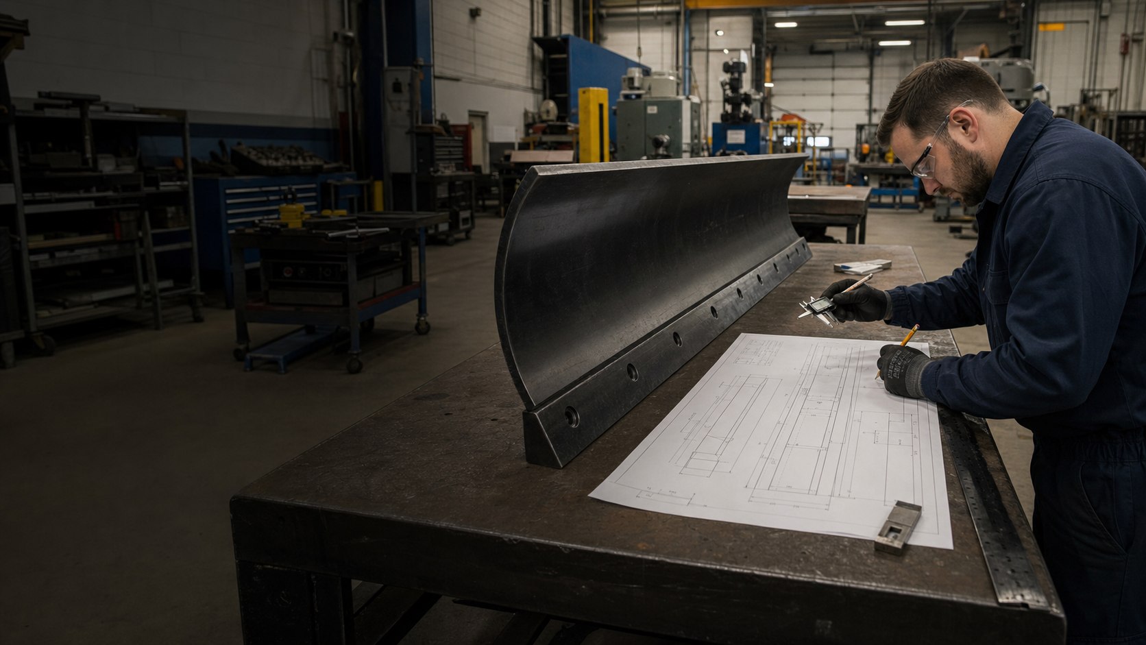
Profile and Dimensions
Holes, Slots and Datums
Material and Application
One Controlled Version
The drawing should remove ambiguity from the custom review. Final tolerances, materials, configuration and commercial terms must be agreed for the actual project.
Show the blade type, complete profile, intended orientation and the equipment or assembly information available to the buyer. Do not rely on a model name alone.
Include overall length, height, thickness and any steps, bends, bevels, radii or end features that affect manufacturing or fit.
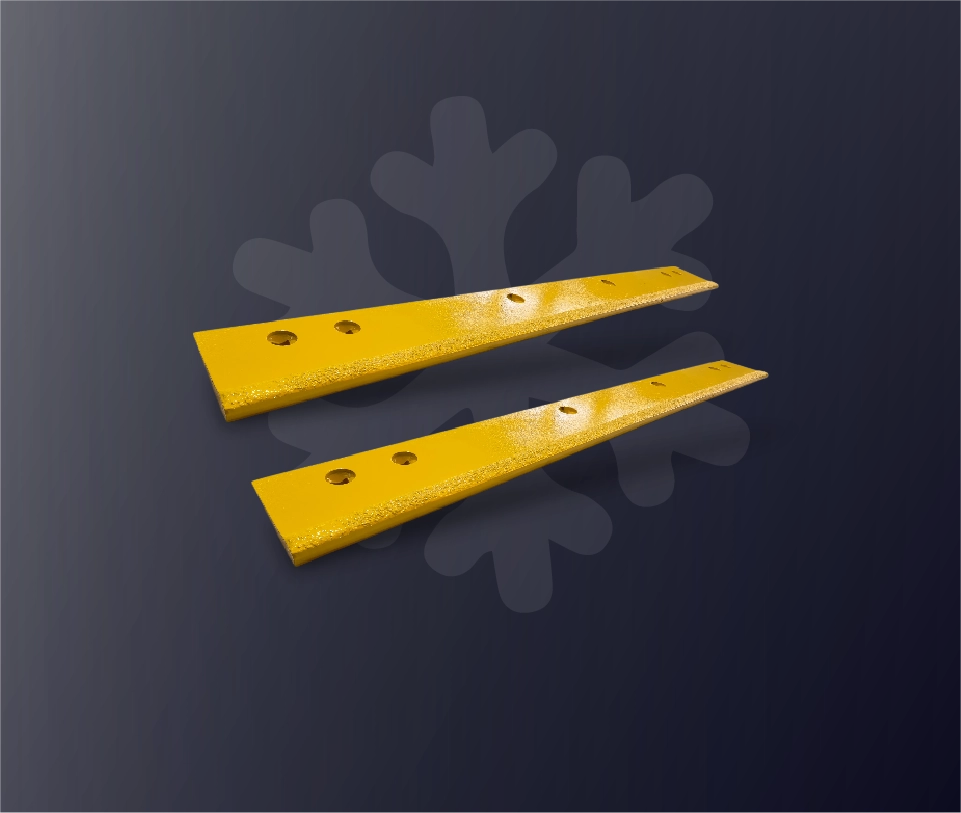
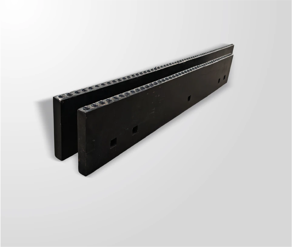
Define every hole or slot from a consistent reference. Show size, shape, quantity, spacing and the position relative to the blade edges.
Use one identifiable drawing version with a part number, revision, date and responsible contact. Clearly mark any change made after the first review.
Collect confirmed information from the drawing, physical sample, installed blade and equipment documentation without filling gaps by assumption.
Provide the drawing title, customer part number, revision and the equipment, moldboard or mounting system information available for the review.
Show the complete blade in enough views to define length, height, thickness, profile, working edge, ends and any non-symmetrical feature.
Record the number of holes or slots, their shape and size, center positions, vertical location and distance from a clearly identified reference end.
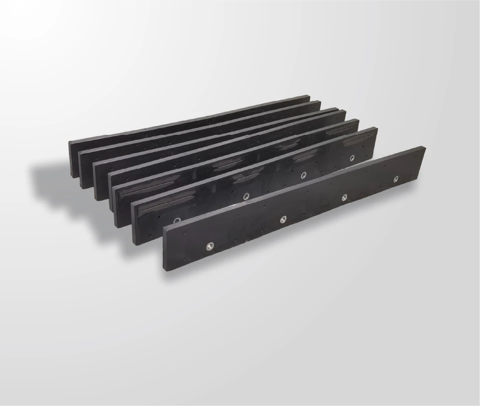
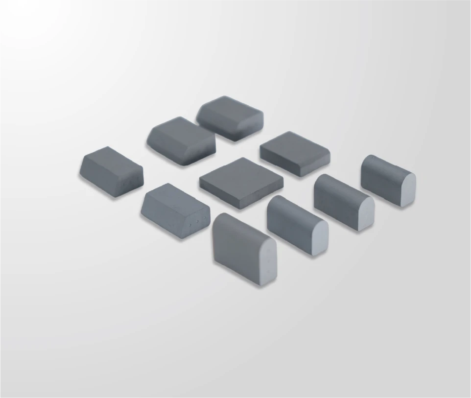
Identify which surfaces, components and cutting-edge areas belong to the requested product. For JOMA-style blades, distinguish the rubber body, steel segments and carbide insert area where relevant.
State the operating equipment, road or surface conditions and any buyer-controlled material, packaging or identification requirement that must be reviewed.
Include the estimated quantity, delivery destination and requested timing for quotation discussion. These details do not replace engineering approval of the drawing.
A useful mounting-pattern drawing does more than list one spacing value. It shows how every feature relates to the same reference end and blade edge.
✓ Identify the reference end and reference edge
✓ Show hole or slot quantity, size and shape
✓ Record center-to-center positions
✓ Record end-to-first-feature position
✓ Show the vertical position from a consistent edge
✓ Mark unused or irregular features clearly
Do not average worn holes or copy uncertain dimensions into a controlled drawing. Flag the uncertainty and provide photographs or a sample for review.
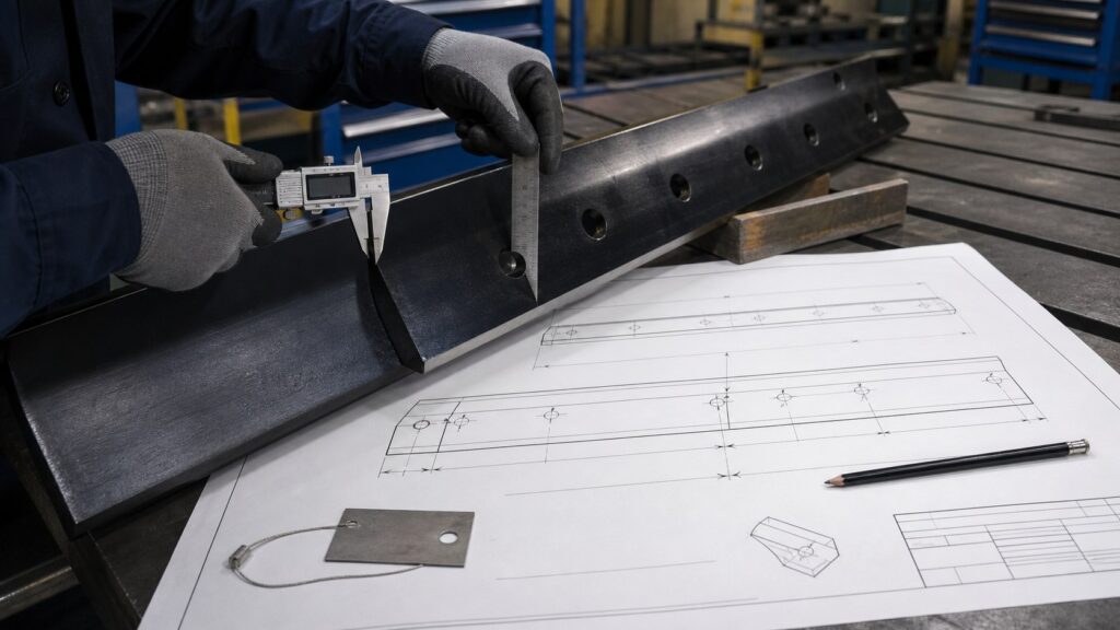
Illustrative drawing-review scene; not an actual SENTHAI facility or customer drawing.
The drawing remains the main technical reference. Supporting files help the engineering team understand orientation, fit and the physical condition of an existing component.
Provide the current revision in a reviewable format. When native CAD is available, include it together with a fixed-view copy for reference and confirm the preferred format with the engineering team.
Add full front and back views, both ends, the mounting pattern and close-ups of unusual features. Keep the same orientation used in the drawing.
A sample can support reverse-engineering or condition review, but it should be identified and its wear or deformation recorded so it is not mistaken for the intended new geometry.
List the application, quantity, destination and unresolved technical questions. Keep this summary aligned with the drawing revision submitted for review.
Resolve or clearly flag each gap instead of allowing an undocumented assumption to enter the custom project.
Hole positions cannot be interpreted consistently when dimensions start from different or unidentified ends and edges.
A spacing value alone does not define quantity, diameter, slot shape, vertical position or the end location of the pattern.
Files with different dimensions but no clear revision history create uncertainty about which geometry should be quoted or reviewed.
Photographs explain the part but do not provide controlled dimensions. Add confirmed measurements and an approved drawing before manufacturing.
The sequence separates preliminary discussion from the final controlled manufacturing requirement.
Send the drawing, photographs, sample information, quantity and application summary available for the initial review.
Resolve missing dimensions, conflicting revisions and uncertain material, mounting or configuration requirements.
Confirm the agreed drawing revision and the project-specific technical and commercial requirements before production authorization.
Keep approved revisions and later changes traceable so production, inspection and future reorders refer to the same requirement.
If no controlled drawing exists, start by measuring the physical blade and photographing it in one consistent orientation. Use those records to support engineering review rather than treating them as final manufacturing instructions.
Project-specific engineering requirements take priority over this general preparation guide.
SENTHAI states that JOMA-style blades and related wear parts can be customized from drawings, samples or required specifications. Feasibility, configuration, price, quantity and delivery must be confirmed for the actual request.
A photograph is useful for orientation and identifying features, but it does not provide controlled dimensions. A confirmed technical drawing is needed before manufacturing requirements can be approved.
Show the number, size and shape of all holes or slots, their center positions, vertical location and distance from a clearly identified reference end and edge.
Not automatically. Record wear, deformation and damage on the sample, then distinguish the measured condition from the intended new geometry during engineering review.
No. Compatibility and feasibility depend on the actual drawing, dimensions, equipment, mounting arrangement, application and approved configuration. Final requirements must be confirmed for the specific project.
Send the latest technical information available for a JOMA-style or custom snow plow blade review.
✓ Drawing and revision reference
✓ Complete blade and mounting photographs
✓ Equipment or application information
✓ Estimated quantity
✓ Delivery country or destination
Email: [email protected]