
Chute and Transfer Point Wear Liners for Hard Rock
A transfer point is usually judged on how much material it spills and how often it stops the plant. Both numbers come back to the same component: the chute wear liner. Liner choice sets…

A transfer point is usually judged on how much material it spills and how often it stops the plant. Both numbers come back to the same component: the chute wear liner. Liner choice sets how long the chute holds its geometry, how much of the discharge velocity it survives, and how much of the impact load reaches the structure behind it. Get the liner family wrong and the symptom appears somewhere else, as wear on the chute shell, a bolted joint working loose, or a throughput loss the control room cannot explain.
This page is for plant and maintenance engineers, contractors and distributors working on conveyor transfers, crusher feed chutes and discharge points in hard-rock duty. It covers where a transfer point actually loses material, which liner families suit which zone, how thickness and coverage are decided, how liners are fixed and accessed, how wear is measured and planned, what fails and why, and how to write a chute liner package as a specification rather than a plate order.
Where a Transfer Point Loses Material
Loss concentrates at the impact point and the discharge lip.
Material arrives at the load point at speed, so impact wear and edge damage cluster there, while sliding abrasion works along the chute floor towards the highest-velocity discharge.
A transfer point is not one wear surface any more than a rotor is. Material leaves the head pulley on a trajectory, strikes the chute at a load point or an impact bed, is redirected by the chute geometry, slides down a floor or a curved section, and leaves past a lip into the next piece of equipment. Each of those zones has a different wear mechanism and therefore needs a different answer.
The load point sees impact plus sliding abrasion, and the load spreads across an area that depends on belt speed, lump size and drop height. The floor of the chute sees sliding abrasion, which rises steeply with velocity and with the angularity and silica content of the rock. The lip and the discharge opening see both, plus the erosion that follows any turbulence where the material stream separates from the surface.
Two secondary losses belong in the same review. A worn or undersized skirt seal lets fines escape along the belt, which turns a liner decision into a housekeeping and belt-wear problem. And a build-up of damp fines on a chute face changes the geometry of the transfer, which then changes where wear concentrates next.
Liner Families and Where Each Fits
The families available divide by what they are good at, and the useful approach is to assign a family to a zone rather than to the whole chute.
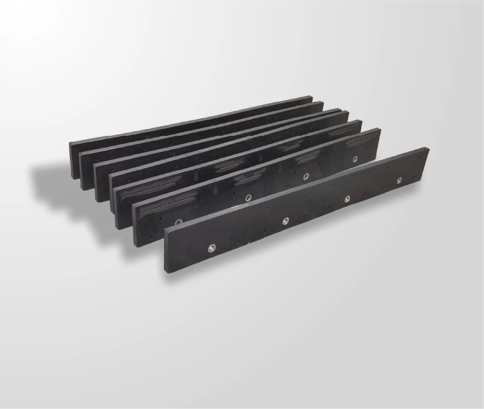
Plain and abrasion-resistant steel plate is the workhorse. It is available in thicker sections, can be cut and drilled in a workshop, and takes bolted fixings predictably. Abrasion-resistant grades are supplied with published abrasion data, which is a more useful basis for comparison than a hardness number alone; the wear-steel producers such as SSAB publish that data for their grades, and general materials reference from ASM International covers how the grades behave under different wear mechanisms.
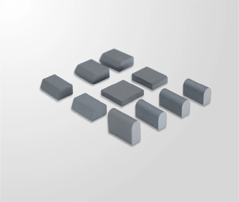
Cast white iron and high-chrome liners hold up better against sliding abrasion than steel plate of the same thickness and are widely used in the load zone, but they are brittle, which limits how much direct impact they can take and makes handling a careful operation. Ceramic and cemented carbide wear elements take abrasion resistance a step further in small, hard tiles or inserts bonded or keyed onto a backing plate, which suits the areas where section is tight and wear is concentrated.
Rubber and polyurethane liners take a different route: a resilient surface absorbs impact and is often used behind a rock box or at a point where a steel liner would be battered rather than worn. The final option is not a material at all but a designed dead bed, where material is allowed to accumulate and wear on itself instead of the chute; it suits high-impact load points where the geometry allows a stable build-up.
| Family | Abrasion resistance | Impact tolerance | Where it usually fits | Fixing method |
|---|---|---|---|---|
| AR steel plate | Moderate to good, thickness dependent | Good | Chute floor, general lining, repairs | Countersunk bolts, welded studs |
| Cast white iron | High | Limited by brittleness | Load zone, high-sliding areas | Bolted, keyed sections |
| Ceramic or carbide tile | Highest | Low unless well backed | Confined high-wear patches | Bonded on backing plate, keyed |
| Rubber or polyurethane | Moderate | High | Impact zones, curved sections | Bolted, bonded, modular tiles |
| Rock box (dead bed) | Self-sacrificing | Highest at the load point | High-impact points with suitable geometry | Designed into the chute structure |
Thickness, Coverage and Loss Allowance
Liner thickness is a life target expressed in millimetres, chosen with the replacement interval in mind rather than copied from a previous installation.
A liner is consumed from its working face inward, so the useful life is the working section minus the thickness that must remain for safety and fixing. That remaining section matters because the fastener heads and the countersink depth live within it: once wear reaches the countersink, the fixing starts to fail rather than the liner. Setting a loss allowance into the specification, and a discard thickness for the zone, is what turns a liner into a planned consumable instead of a discovery.
Coverage is usually decided by where the material actually travels rather than by where the chute looks thin. Wear spreads from the load point outward and along the flow path, so the lined area should extend beyond the currently worn patch, with overlaps and edge details designed so that a plate edge never presents a step into the flow. Material standards and test methods published by ASTM are the reference for verifying the properties claimed for a liner grade, including where hardness alone does not describe abrasion performance.
Fixing Methods and Access
Fixing decides whether the liner stays in place under load, and access decides how long the change takes; both belong in the specification alongside the material.
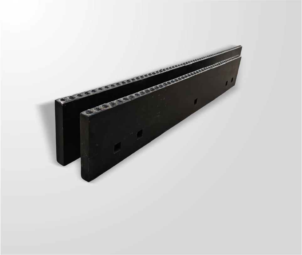
Countersunk bolts are the common fixing on steel liners, because the head sits below the working surface. Countersink depth has to match the fastener or the head stands proud, wears, and cannot be undone. Welded studs and plug welds are used where a liner has to be fitted from one side, and keyed or bonded systems are used for ceramic and rubber elements. In impact zones, no fixing pattern compensates for a family that cannot take the load, which is why the load point is often designed as a dead bed instead.
Access is a design decision that is usually made too late. Inspection hatches, platforms and isolation points determine whether a crew can measure liner thickness safely or only by stopping the plant for a shift. Working on a chute while a conveyor is isolated is a safety matter with formal requirements for lockout and access on mine sites under 30 CFR, and the practical consequence is that a chute designed for access gets measured far more often than one that is not.
Wear Measurement and Planning
Wear planning rests on measurement at fixed points rather than on visual inspection, because a liner that looks serviceable at one point can be close to discard thickness at another.
The method is straightforward. Mark a grid on each liner zone, measure thickness at the same points each time with a depth gauge or an ultrasonic thickness gauge on the backing, and record it against tonnage and hours. Two or three readings per zone produce a wear rate, and a wear rate turns replacement into a scheduled event. Paint or mark the discard thickness on the drawing so that a technician can compare without calculation.
The same records feed back into design. If the load point is the only area being consumed, the answer may be a thicker plate there, a different family, or a dead bed; if the whole floor is wearing evenly, the answer is usually section. Where the wear rate is dominated by high-velocity sliding abrasion, materials guidance such as the wear and corrosion protection resources published by AMPP is useful context for selecting between a hard-facing approach and a replaceable liner.
Failure Modes and Their Causes
Most chute liner failures are attributable to a small number of causes, and the pattern is worth reading before the next plate is ordered.
| Failure seen | Likely cause | Corrective action |
|---|---|---|
| Plate worn through at one patch | Load concentrated at a point, or thickness set from a general figure | Increase section locally, or change family in that zone |
| Fasteners worn flush or lost | Countersink depth mismatched to the bolt, or wear reached the fixing line | Match countersink to fastener, set a discard thickness |
| Liner torn off under load | Family or fixing unable to take the impact energy | Dead bed, resilient liner, or heavier fixing pattern |
| Cracks in a cast liner | Impact load on a brittle material | Move cast iron away from the load point |
| Build-up changing the flow | Moisture, insufficient slope, or a sticky liner surface | Geometry change, lower-friction liner, or a designed dead bed |
Two of these failures are frequently misread. A fastener failure looks like a liner failure and is really a specification failure, because the countersink and the discard thickness were never written down. And a build-up problem looks like a material problem when it is usually a geometry problem: a chute that carries damp fines needs either more slope or a surface the material does not adhere to.
Specifying a Chute Liner Package
A chute liner package is a document per transfer point, not a list of plates. It should define the geometry, assign a liner family to each zone, and state the thickness, fixing and discard criteria that make the package maintainable.
- Geometry. The chute drawing with load point, flow path and discharge opening identified, and the material trajectory taken from belt speed and lump size.
- Zone assignment. Family, thickness and fixing for each zone, with the reason recorded so the next person can see why.
- Fixing specification. Fastener type, countersink depth, pattern and the torque method, matching the liner family.
- Discard criteria. The minimum safe section per zone, marked on the drawing.
- Documentation and spares. Material data for each liner grade, batch identification, and the spares held against the highest-wear zones.
Getting there usually requires plant data rather than a catalogue. Aggregate producers’ bodies such as NSSGA publish operational material that helps a plant benchmark how much it moves and what availability is worth, which is the context a maintenance planner needs when justifying a liner upgrade against a like-for-like plate replacement.
The decision inside a transfer point is not which liner is the hardest or the cheapest, but which liner belongs in which zone. Wear concentrates at the load point and the discharge lip, so impact tolerance and abrasion resistance are needed in different places, sometimes in the same chute. Thickness and coverage should be set from a life target with a stated loss allowance, fixing selected with the countersink and discard thickness written down, and measurement taken at fixed points against tonnage so replacement becomes scheduled rather than discovered.
Send SENTHAI the chute drawing, the material trajectory, and the wear measurements or photographs from the last liner set, and the technical team will review the family selection, thickness, fixing pattern and discard criteria for each zone of the transfer point.
Related reading: the wider consumable picture is set out in wear parts beyond plows.
Frequently Asked Questions
What is a chute in a conveyor transfer point?
It is the lined duct that catches material leaving a head pulley and redirects it into the next piece of equipment. The liner is the replaceable wear surface inside it, and the chute shell is the structure behind the liner. A transfer point is judged on spillage and stoppages, and both depend on how well the liner holds its geometry and survives the impact of the load point.
Which liner material suits the load point of a chute?
The load point sees impact as well as sliding abrasion, so it is the zone where brittle materials are most exposed. Cast white iron and ceramic tile resist abrasion well but tolerate limited direct impact, so they are usually paired with a resilient rubber or polyurethane surface, a heavier steel section, or a designed dead bed that lets material accumulate and absorb the energy. Assigning a family per zone is more effective than lining the whole chute in one material.
How thick should a chute wear liner be?
Thickness is a life target, not a single published figure. The working section is set by the duty and the replacement interval the plant wants, then a loss allowance is subtracted for the thickness that must remain for safety and for the countersink of the fixings. The minimum safe section per zone belongs on the drawing as a discard criterion, so a technician can compare a measurement against it without calculation.
How often should chute liners be measured?
Measure at fixed points on a marked grid, two or three readings per zone, and tie the readings to tonnage and hours. That produces a wear rate, and the wear rate sets the interval rather than a calendar. Zones where the fixings sit closest to the working surface should be measured most often, because once wear reaches the countersink the fixing starts to fail rather than the liner.
What are the ordering terms for a chute liner package?
A package is quoted against the chute drawing, the zone assignments, the liner grades and the fixing specification. Batch quantities, lead time, packing and delivery terms are agreed per order and are stated in the written quotation or order documents. Material data and batch identification for each liner grade are confirmed with the quotation, so the delivery can be checked on receipt against the same specification the plant ordered from.
{
“@context”: “https://schema.org”,
“@type”: “FAQPage”,
“mainEntity”: [
{
“@type”: “Question”,
“name”: “What is a chute in a conveyor transfer point?”,
“acceptedAnswer”: {
“@type”: “Answer”,
“text”: “It is the lined duct that catches material leaving a head pulley and redirects it into the next piece of equipment. The liner is the replaceable wear surface inside it, and the chute shell is the structure behind the liner. A transfer point is judged on spillage and stoppages, and both depend on how well the liner holds its geometry and survives the impact of the load point.”
}
},
{
“@type”: “Question”,
“name”: “Which liner material suits the load point of a chute?”,
“acceptedAnswer”: {
“@type”: “Answer”,
“text”: “The load point sees impact as well as sliding abrasion, so it is the zone where brittle materials are most exposed. Cast white iron and ceramic tile resist abrasion well but tolerate limited direct impact, so they are usually paired with a resilient rubber or polyurethane surface, a heavier steel section, or a designed dead bed that lets material accumulate and absorb the energy. Assigning a family per zone is more effective than lining the whole chute in one material.”
}
},
{
“@type”: “Question”,
“name”: “How thick should a chute wear liner be?”,
“acceptedAnswer”: {
“@type”: “Answer”,
“text”: “Thickness is a life target, not a single published figure. The working section is set by the duty and the replacement interval the plant wants, then a loss allowance is subtracted for the thickness that must remain for safety and for the countersink of the fixings. The minimum safe section per zone belongs on the drawing as a discard criterion, so a technician can compare a measurement against it without calculation.”
}
},
{
“@type”: “Question”,
“name”: “How often should chute liners be measured?”,
“acceptedAnswer”: {
“@type”: “Answer”,
“text”: “Measure at fixed points on a marked grid, two or three readings per zone, and tie the readings to tonnage and hours. That produces a wear rate, and the wear rate sets the interval rather than a calendar. Zones where the fixings sit closest to the working surface should be measured most often, because once wear reaches the countersink the fixing starts to fail rather than the liner.”
}
},
{
“@type”: “Question”,
“name”: “What are the ordering terms for a chute liner package?”,
“acceptedAnswer”: {
“@type”: “Answer”,
“text”: “A package is quoted against the chute drawing, the zone assignments, the liner grades and the fixing specification. Batch quantities, lead time, packing and delivery terms are agreed per order and are stated in the written quotation or order documents. Material data and batch identification for each liner grade are confirmed with the quotation, so the delivery can be checked on receipt against the same specification the plant ordered from.”
}
}
]
}


