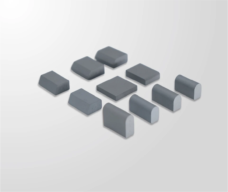
Carbide Insert Wear Patterns: Reading Them Before Failure
How to read carbide insert wear patterns in service: even loss, scalloping, chipping and joint movement, and the remedy each pattern calls for.

An insert that has worn evenly and an insert that has been knocked out of place look similar from a distance and mean completely different things. Reading the pattern is the step that decides whether the fleet changes material, changes fitment or changes nothing, and it costs nothing to perform as part of a rotation check.
What Carbide Insert Wear Patterns Tell You
The pattern identifies the mechanism, not just the amount.
Even loss across the working width indicates abrasion. Localised loss, scalloping or chipping indicates contact or shock problems. Movement and detachment with little wear indicate retention. Each points to a different remedy.
The value of the reading comes from that separation. A fleet that responds to every poor result by changing grade will spend several seasons changing a variable that was never the cause. A fleet that separates the mechanisms addresses the actual problem, which is usually cheaper: a fitment check, a hardware correction or a seating inspection rather than a material change.
The reading also produces the measurement that makes the replacement decision. Even loss at fixed points converts into an interval; chipping converts into a position record, which is what shows whether problems cluster at the ends of a blade, at particular mounting positions or on a specific route. The general question of when inserts reach the end of their service is covered in the material on carbide insert wear.
Wear Patterns and What Each One Signals
Four patterns cover most findings in service. Even reduction across all inserts indicates abrasion and a normal interval, with the useful output being the measured rate. Loss concentrated at the ends of the working width suggests alignment, carrier or contact-pressure issues rather than material, because the ends load differently from the centre on most moldboards.
Chipping or fracture on a subset of inserts points to shock loading. The position matters: damage on the inserts that meet rail crossings or pavement breaks on a specific route indicates the surface, while damage at the same relative position across several different blades indicates the equipment. Movement or detachment with inserts otherwise intact is a retention signature, and it is read along the bond line rather than at the wear face.
Two less common patterns are worth recognising. Inserts sitting proud of their neighbours after fitting or partial wear concentrate load on one corner and originate in seating rather than in material; the mechanism is described in the analysis of seating failure with trapezoid inserts. And a polished, glazed appearance on inserts that have little measurable wear usually indicates that the edge is not cutting into the surface, which is a contact problem rather than a wear problem.
A third pattern is easy to overlook because it looks like success. Where a blade returns with inserts that have worn evenly but the measured amount is larger at the ends than in the centre, the fleet has both a normal interval and a distribution issue. The cause is usually a moldboard that is not flat, a mounting face that has distorted, or a carrier whose down-pressure is uneven along the working width. Correcting the equipment extends the interval without any change to the specification.
Inspection Points and What to Record on Insert Wear Patterns
An inspection that produces usable records follows the same sequence each time: check joint condition and fastener preload first, then examine the insert faces, then measure at the fixed reference points, then photograph from the standard position. Starting with joints avoids measuring edges that are already due to come off for retention reasons.
Four records make the pattern interpretable. The position of every insert with abnormal wear or damage, rather than a count. The measured height at the fixed points. The condition of the bond line, noted as sound, questionable or failed. And the route and hours the edge covered, since the same pattern means different things on an abrasive route and a route with embedded debris.
The position record is the one that produces insight. Damage at the same position across different blades and different trucks indicates the equipment or the route; damage at random positions indicates the surface. Where the fleet has a training routine for inspection, consistency of the reading improves quickly, and the approach is covered in the material on carbide blade inspection training.
Conditions That Produce Each Pattern
Abrasive surfaces produce even loss and predictable intervals. Unsealed gravel, abrasive wind-packed snow and routes where grit is spread all consume material steadily, and the remedy is reserve, grade and interval rather than diagnosis. Surfaces with embedded debris produce chipping and localised damage, and the remedy involves grade, retention quality and, where the problem is severe, an honest look at how the route is being worked.
Refrozen, hard-packed surfaces produce the pattern fleets most often misread: little measurable wear with poor clearing and elevated down-pressure. The compensating behaviour loads the trip mechanism and the mountings, so the evidence of a contact problem appears in the machine rather than on the inserts. Maintenance practice on ice-affected networks is a recurring subject in the pooled research published by Clear Roads.
Treatment practice changes the surface in ways worth recording. Where abrasives are spread, the material itself contributes to wear; where liquid de-icing is applied ahead of a freeze, the resulting surface may be harder than a dry-salt scenario. Recording what was applied alongside the pattern is what allows two similar routes to be compared meaningfully, and material behaviour under those conditions is described in the applications material published by the International Tungsten Industry Association.
Rotating, Replacing or Investigating
The pattern should lead to one of three actions. Where wear is even and the joints are sound, the action is rotation or replacement on the measured interval. Where the pattern indicates fitment, seating or alignment, the action is to investigate the equipment before fitting anything new, because the replacement edge will follow the same path. Where the pattern indicates retention failure, the action is to review the production record for the batch along with the fitting records.
Replacing inserts individually makes the action more granular but does not change the logic. A blade that has chipped at one position can be returned to service with the damaged insert replaced and the cause documented; a blade with movement developing across several positions should be treated as an assembly rather than patched. The process of joining new inserts to an existing body is described in technical terms by TWI, and it requires controlled heat, correct filler and clean surfaces, which is rarely available at the roadside.
Whichever action is taken, the record should state the reason. Retired for even wear, retired after damage and replaced for retention failure are three different outcomes, and only the first belongs in an interval calculation. Where damaged and worn edges are counted together, the fleet’s own model records a maintenance problem as a wear result and the comparison against a different specification becomes misleading.
Tools and Safe Handling During Inspection
The tool kit is short: a straight edge or gauge, a light, a torque wrench and hand protection for load testing inserts. Availability at the point of work matters more than the equipment itself, because an inspection that requires a trip to the stores is deferred in the busiest weeks. General workshop requirements for hand and power tool use are set out in the OSHA occupational safety and health standards.
Handling is the larger risk, since edges are heavy and inspections often take place at the end of a shift. Load assessment principles are published by the UK Health and Safety Executive. Photographs taken before any cleaning are equally important from an evidence perspective, because the surface condition is part of the reading and cannot be recovered once the edge is washed.
Grade and dimensional questions that arise from a pattern should be resolved against documents rather than impressions. Test methods published by ASTM allow a hardness or grain-size claim to be checked, and SENTHAI works to plus or minus 0.02 mm dimensional tolerances on carbide components with fitment validated against AASHTO and DIN bolt patterns through AASHTO standards and DIN.

Recording Patterns Across the Fleet
Patterns become visible when records are comparable across trucks. One row per blade per inspection, containing the date, truck, route class, position of any abnormal insert, measured heights and joint condition, is enough to identify whether a problem is local to a truck, a route or a production batch. Without that structure, each finding is an anecdote and the diagnosis starts from scratch every time.
The review should be periodic rather than continuous. At the end of the season, sorting the records by position and by truck shows whether failures cluster, and clustering is what points to the owner of the problem: equipment, route, specification or supply. That review is also the point at which a specification change can be justified or rejected on evidence.
Insert wear patterns separate abrasion, shock, retention and contact problems, and each has a different remedy. Only one of the four is addressed by changing the material, which is why the reading matters more than the response.
Inspect joints first, measure at fixed points, record positions and photograph before cleaning. Sorted at the end of a season, those records show where problems cluster and allow the next specification decision to be made on evidence rather than on impression.
Send SENTHAI photographs of worn and damaged inserts together with their positions on the blade, and the technical team will review the wear mechanism, grade and fitment for the routes involved.
Frequently Asked Questions
What does chipping on a few inserts indicate?
Chipping usually indicates shock loading rather than abrasion. Where the damaged inserts sit at the same position across different blades, the cause is likely the equipment or a specific route feature such as crossings or pavement breaks. Where damage is spread randomly, the surface conditions are the likely cause. Establish the pattern before changing grade, because grade addresses only one of those possibilities.
Why do inserts show little wear but the blade clears poorly?
That combination points to loss of contact rather than wear. On hard, refrozen surfaces the edge can ride over the surface, retaining material while clearing poorly and encouraging operators to add down-pressure. Measure insert height at fixed points to confirm material remains, then review contact, geometry and carrier down-pressure rather than ordering replacements.
Should damaged inserts be replaced individually or as an assembly?
An isolated damaged insert can be replaced where the surrounding joint is sound, provided the work is done with controlled heat, correct filler and clean surfaces. Where movement is developing along several positions, or a section of the bond has failed, the assembly should be treated as unserviceable, because continuing to run it transfers unpredictable load into the blade body and mounting face.
How should wear patterns be recorded for later comparison?
Record the position of every insert with abnormal wear or damage rather than a count, together with measured heights at fixed points, joint condition and the route and hours covered. Photograph the blade before cleaning. Sorting those records by position and by truck at the end of the season is what reveals whether problems cluster by equipment, route or production batch.