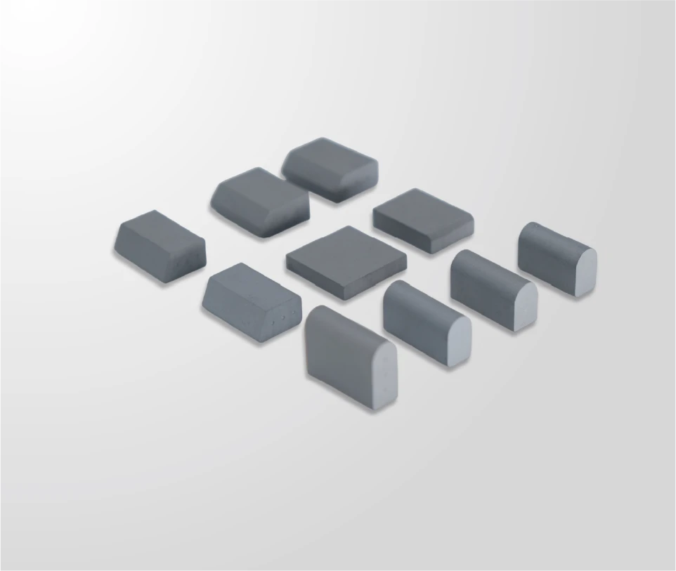
Carbide Insert Spacing: Density Along the Cutting Edge
Carbide insert spacing explained: how density along the cutting edge affects contact, cost per metre, fitment and the interval between rotations.

Insert spacing is the specification point that decides how much carbide a blade carries and where it sits, and it is often inherited rather than chosen. A fleet that changes insert count to extend an interval is changing mass at the leading edge, cost per metre and the load carried into the blade body at the same time. Spacing is worth specifying deliberately because all three consequences arrive together.
Which Carbide Insert Spacing Points Decide Performance
Spacing, count and position decide how carbide is used.
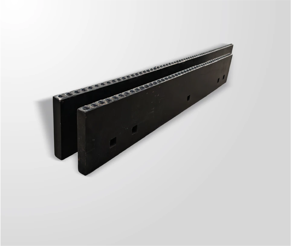
Spacing sets the distance between inserts along the working width, count follows from spacing and blade length, and position determines which parts of the edge carry carbide through the interval between rotations.
The three are related but not interchangeable, which is why a specification should state spacing and the arrangement rather than a total insert count. Two blades with the same number of inserts can place them differently across the working width and produce different contact behaviour. Where inserts are concentrated at the positions that meet the hardest surface, the interval can extend; where the arrangement leaves the ends of the blade sparsely covered, those positions become the limiting factor.
Reading the arrangement alongside the shape is worth doing before changing anything. The available geometry options are compared in the material on insert shapes, and the general specification process is covered in the guidance on how to specify a carbide snow plow blade. Spacing interacts with both, because a shape that spreads contact across a wider band behaves differently at a given spacing than a directional profile does.
How Spacing Interacts With Edge Geometry and Down-Pressure
Closer spacing concentrates load and raises edge cost.
Reducing the gap between inserts places more carbide at the contact area, which can extend the interval between rotations, at higher cost per metre of edge and with more mass at the leading edge. Both effects are real and both belong in the specification decision.
The down-pressure interaction is the one most often missed. Additional mass at the leading edge changes how the blade meets the surface, and on a lighter carrier the available down-pressure may no longer be sufficient to maintain contact. The result is a blade that carries more carbide but clears less effectively, which prompts compensating behaviour from the operator and can accelerate wear on the machine. On a heavy carrier with weight to spare, the same change is absorbed.
The geometry interaction runs in the same direction. A directional insert concentrates contact along a narrow band, so spacing changes have a stronger effect on how much material works at the surface than they do with a rounded profile that spreads contact more widely. Where a fleet is considering both a shape change and a spacing change, the two should be evaluated separately, because changing both at once makes it impossible to attribute the result.
There is one further relationship worth knowing before a spacing change is proposed. Contact pressure at the surface depends on the load applied and the area carrying it, so adding inserts across the same working width changes the distribution of pressure along the edge. Where the goal is better clearing on a hard surface, the additional carbide may achieve it; where the goal is a longer interval on an abrasive surface, the same change may simply distribute wear that was already even. Understanding which objective is being pursued is what determines whether spacing is the right lever.
Grade, Geometry and Material Choices Alongside Spacing
Spacing changes the demand on the material. Where inserts are closer together, each one carries a smaller share of the load under normal scraping but the assembly behaves more like a continuous cutting edge at the surface, which alters the shock it transmits when it meets an obstruction. Where spacing is wider, individual inserts carry more load and the grade’s toughness matters more at each contact.
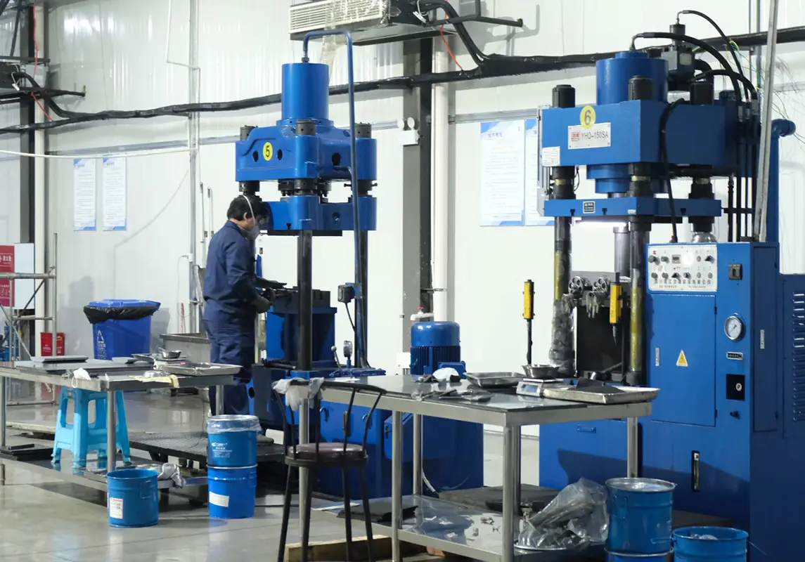
SENTHAI engineers the hardness and toughness balance for stated service conditions using hardness on the HRA scale together with carbide grain size, and supplies micro grain inserts in trapezoid and bullnose shapes. Because grade and shape are specified together rather than chosen independently, a spacing change can be evaluated against the material that will actually carry it. The manufacturing chain runs in-house in Rayong, Thailand, in a US-invested plant using non-China raw materials, from wet grinding and robotic pressing at up to 500 tons through vacuum and low-pressure sintering, automated high-temperature induction brazing and finishing.
The relationship between spacing and retention also deserves attention. More inserts mean more joints across the same working width, and every joint is a position where load must transfer from carbide into the steel body. Where spacing is reduced, the quality of each joint matters more in aggregate, even though the load per insert is lower. Background on the joining process is published by TWI, and material guidance on tungsten and cemented carbide applications is available from the International Tungsten Industry Association.
Fitment and Tolerance Requirements for Spacing Changes
A spacing change is a change to the blade, not just to the insert count. SENTHAI validates fitment against AASHTO and DIN bolt patterns before release and works to plus or minus 0.02 mm dimensional tolerances on carbide components, with AASHTO published standards as the reference for agency specifications and DIN covering European and export conventions.
Three consequences follow from adding or removing inserts. First, the position of each insert relative to the mounting holes changes, which affects how load is distributed into the mounting face. Second, the mass of the assembly changes, which may alter the hardware requirement and the seated height of the edge. Third, the arrangement must remain compatible with the blade profile, because inserts are positioned relative to the working face rather than to a nominal centre line.
Before ordering a spacing change, confirm the arrangement in writing against the drawing, along with the hardware set required and the seated height of the assembly. Where inserts are supplied separately for fitting into existing blades, confirm the tolerance held at the locating features, because a small variation across a greater number of positions compounds into visible unevenness along the edge.
Quality Evidence to Request With an Insert Spacing Quote
Spacing makes documentation straightforward to request, because it is measurable. Ask for the arrangement drawing showing insert positions, the dimensional inspection results for the delivered assembly at those positions, and the tolerance held at the locating features. SENTHAI inspects and archives every batch, so these records are available on request; the quality control and traceability page describes what they contain.
Two further items complete the package. Grade data for the inserts, referenced to a test method such as those published by ASTM, since spacing and grade are specified as a pair. And a statement of the retention method and how bond integrity is controlled, because more inserts across the same working width means more joints carrying load into the body. Materials engineering resources published by ASM International are useful when a non-specialist has to review a grade claim against a specification.

Common Spacing Errors and Their Cost
The most common error is specifying a total insert count rather than an arrangement. Two suppliers can satisfy a count requirement with different distributions across the working width, and the blades will not perform identically. The second is adding inserts to extend an interval without checking whether the carrier can maintain contact with the additional mass, which produces a heavier edge that clears less well.
The third error is changing spacing and grade at the same time. When the result is better, nobody knows which change caused it; when it is worse, both are suspects and the fleet spends another season resolving it. Changing one variable at a time is slower in the first season and faster overall. The fourth is leaving the arrangement unverified on receipt, which allows a delivery to differ from the drawing without being detected until the edge is fitted.
The costs of these errors are concentrated in the interval and in the machine. A heavier-than-intended edge adds cost per metre and may increase hardware work; a differently arranged edge changes the interval without an operational reason. Both are avoidable with an arrangement drawing and a receiving check against it.
Writing the Spacing Requirement Into a Tender
A tender should state the arrangement rather than the count: insert type, the spacing between positions, and the position of each insert relative to the mounting holes. Add the tolerance at the locating features, the profile the inserts must fit, the grade requirement with its properties, and the retention method. Where a fleet runs several vehicle groups, state the arrangement for each rather than a single fleet value.
Require the bidder to confirm that the arrangement matches the blade drawing and that the hardware set is suitable for the assembly’s mass. Where the programme references published patterns, citing the relevant AASHTO standards and requiring a declaration of conformity keeps offers comparable. One clause is worth adding: require the supplier to state any change in hardware requirement that the specified arrangement introduces, so the workshop can be prepared before the first delivery arrives.
Insert spacing decides how much carbide works at the surface, where it sits and what it costs per metre. It interacts directly with down-pressure, insert shape and retention, which is why it belongs in the specification rather than in a supplier’s default.
State the arrangement rather than the count, confirm the hardware and seated height that follow from it, and require the arrangement drawing with the delivery. Changed one variable at a time and measured against the interval, spacing becomes a specification decision the fleet can defend.
Send SENTHAI your blade drawing, carrier classes and current insert arrangement, and the technical team will review the spacing, shape and grade combination for each group.
Frequently Asked Questions
Does closer insert spacing always extend the interval between rotations?
It increases the amount of carbide working at the surface, which can extend the interval where contact is maintained. It also adds cost per metre and mass at the leading edge, and on a lighter carrier the additional mass can reduce contact pressure. The effect depends on the carrier and the surface, which is why spacing changes are best trialled on a defined truck group and measured.
Should spacing be specified as a count or as a distance?
Specify the arrangement: insert type, the spacing between positions and the position of each insert relative to the mounting holes. A total count can be met with several different distributions across the working width, and those arrangements behave differently. The arrangement drawing is also what a receiving inspection can check against the delivery.
Can insert spacing be changed on existing blades?
It can where the blade body accommodates the new positions, but it is a design question rather than a parts swap. The insert positions relative to the mounting holes change, the assembly mass changes and the hardware requirement may change with it. Ask the supplier to confirm the arrangement against the drawing and to state any hardware implications before the change is made.
How does spacing affect the cost per metre of edge?
More inserts across the same working width raise the purchase cost per metre and reduce the amount of material retired if individual inserts can be replaced. The net effect depends on whether the interval extends and how the assembly is serviced. Model it per truck group using measured intervals, and change one variable at a time so the result can be attributed.