
Carbide Insert Tolerance: Why Fitment Starts at the Drawing
Carbide insert tolerance explained: how dimensional control at the locating features decides seating, retention and fitment across blade patterns.

Tolerance is the least visible item on a quotation and the one most likely to cause a return. Two inserts can match on every nominal dimension and still fit differently, because it is the tolerance held at the locating features that decides whether an insert seats flat or sits proud and concentrates load on one corner. On a blade that carries thousands of load cycles per season, that difference decides retention.
Which Carbide Insert Tolerance Points Decide Fitment
Tolerance at the locating features decides seating.
The dimensions that position the insert, rather than its overall size, determine whether it sits flat in the pocket or stands proud. Nominal dimensions that agree are not evidence that two parts will assemble the same way.
Three dimensional groups matter. The locating features that position the insert relative to the blade, the insert’s base geometry where it meets the seating surface, and the cutting face dimensions that determine the working profile. Tolerances on the first two decide fitment; tolerances on the third decide how the worn edge presents to the surface. A supplier can hold the working profile and still miss the locating features, which is why a drawing with tolerances on both is what makes a specification enforceable.
SENTHAI works to plus or minus 0.02 mm dimensional tolerances on carbide components and validates fitment against AASHTO and DIN bolt patterns before release, with AASHTO published standards as the reference for agency specifications and DIN covering European and export conventions. Stating a tolerance as a figure without a method of verification leaves it unenforceable, and the receiving inspection described on the quality control and traceability page is where that becomes visible.
How Tolerance Interacts With Seating and Retention
An insert that does not seat flat loads one corner.
Where tolerance variation leaves an insert proud or tilted, contact is concentrated on a fraction of the base, and the joint beneath it carries stress it was not designed for. That concentration is what turns a fitting issue into a retention failure.
The mechanism is worth stating plainly because it explains a common pattern. An edge returns with inserts detached but otherwise intact, and the fleet concludes that the material is wrong. In fact the bond was sound; it was loaded unevenly because the insert did not sit flat, and the same thing would happen to a harder or a tougher grade. The same mechanism is described from the seating side in the analysis of edge seating failure.
Tolerance also interacts with the pocket or seat in the blade. Where a seat has deformed through service, a correctly toleranced insert will not seat properly either, and the fleet then faces a choice between repairing the body and replacing the assembly. Checking both sides of the interface—the insert and the seat—is what identifies where the variation actually lies.
Grade, Geometry and Material Choices Around Tolerance
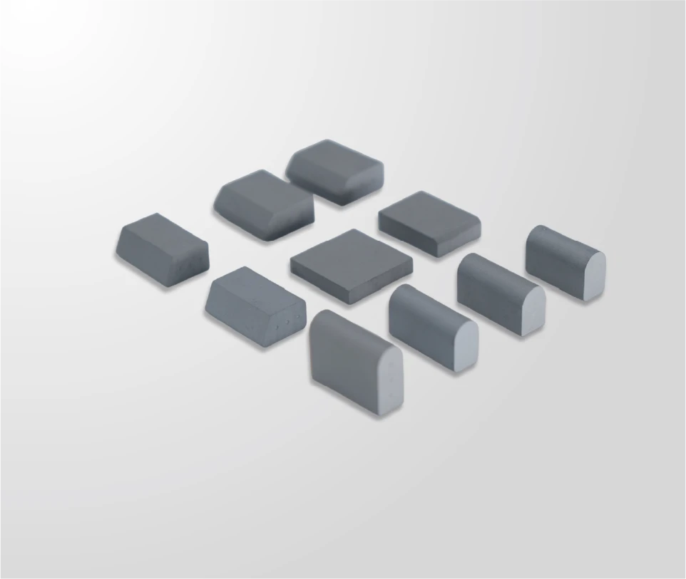
Grade and tolerance are separate requirements that both belong on the drawing. Hardness and grain size determine how the material resists wear and shock, while tolerance determines how it seats and how load reaches the joint. SENTHAI engineers the hardness and toughness balance against stated service conditions using hardness on the HRA scale together with carbide grain size, and supplies micro grain inserts in trapezoid and bullnose profiles so that grade follows geometry rather than being chosen independently.
Production control is what makes a tolerance repeatable across orders. The manufacturing chain at SENTHAI’s Rayong, Thailand facility is in-house, in a US-invested plant using non-China raw materials, running from wet grinding and robotic pressing at up to 500 tons through vacuum and low-pressure sintering, automated high-temperature induction brazing and finishing. Where pressing and finishing are controlled in the same facility as the drawing, the tolerance on a follow-on order is a process output rather than a negotiation.
Sintering behaviour is the reason tolerance is not simply a matter of machining to size. Cemented carbide shrinks during sintering, and the amount depends on grade and grain size, so a change of grade can move finished dimensions unless the process accounts for it. That relationship is why a grade change should be treated as a specification change with a dimensional review, not as a material substitution. Background on material behaviour is published by the International Tungsten Industry Association.
Fitment and Tolerance Requirements Across Blade Profiles
Fitment requirements differ by profile. A directional trapezoid insert located relative to the working face presents contact along a narrow band, so a small positional variation has a visible effect on which part of the insert does the work. A bullnose profile spreads contact across a curved face and tolerates slight positional variation better, which is one reason rounded geometry appears on equipment working variable surfaces.
Those differences do not change the need for a stated tolerance; they change what the tolerance has to protect. For a directional profile, positional tolerance relative to the working face is the critical item. For a rounded profile, the base geometry and seat condition matter more, because load is distributed across a wider area and an uneven seat produces correspondingly uneven load. In both cases, the requirement is expressed on the drawing in a form a supplier can produce and a fleet can check.
Where inserts are supplied for retrofit into existing blades, the fleet should confirm the seat dimensions before ordering rather than after. Where complete assemblies are supplied, fitment validation against the pattern covers the interface. Both routes end in the same place: a written confirmation that the delivered part matches the drawing within the stated tolerance.
Evidence to Request With the Carbide Insert Tolerance Quote
Tolerance is verifiable, which makes documentation the fastest way to compare suppliers. Ask for the dimensional inspection results for the delivered parts at the locating features and the working face, the tolerance to which they were held, and the method used to measure them. SENTHAI inspects and archives every batch, so this record is a routine output rather than a special request.
Three items complete the package. Grade data for the inserts, referenced to a test method such as those published by ASTM, since a grade change can move dimensions through sintering behaviour. A description of the retention method and how bond integrity is controlled, for which technical background is published by TWI. And a fitment confirmation against the blade pattern or seat dimensions supplied. Where a fleet has to review a grade claim without a materials engineer, the resources published by ASM International provide a workable starting point.

Common Tolerance Errors and Their Cost
The most common error is specifying a nominal dimension without a tolerance band. A part made to the nominal value with no band cannot be rejected, however badly it fits, because no requirement has been breached. The second is stating a tolerance on overall size while leaving the locating features uncontrolled, which produces inserts that match a drawing in the dimensions easiest to measure and miss in the dimensions that matter.
The third is accepting a near match on a retrofit. A replacement insert that is close in overall size but different at the locating features will seat badly, and the resulting retention failures will be attributed to the material. The fourth is failing to check the seat in the blade. Where the seat has deformed, even a perfectly made insert will not seat, and the fleet will keep replacing inserts to solve a body problem.
The cost of these errors is concentrated in unplanned replacements and in the diagnostic time spent on them. Each failed insert replacement consumes workshop hours and interrupts service; each misdiagnosis extends the problem into another season. Tolerance statements and a receiving check cost a fraction of that and remove the ambiguity entirely.
A fifth error is more subtle: allowing the same specification number to cover inserts produced to two different tolerance bands. This commonly happens when a fleet accepts a substitute from a second supplier to cover a shortage, and it leaves the fleet unable to tell whether a later failure came from the part or from the substitution. Where a second source is used, it should be quoted against the same drawing and the same tolerance bands, and the records should note which supplier produced each batch.
Writing the Tolerance Requirement Into a Tender
A tender should state tolerances against the features that decide fitment. Give the locating dimensions with their bands, the base geometry tolerance, and the working face dimensions, then state the measurement method. Add the pattern or seat dimensions the insert must match, the grade requirement with its properties, and the retention method. Where a fleet runs several blade profiles, state the tolerance requirement for each rather than one generic value.
Where an equivalent insert is permitted, define the properties and tolerances the equivalent must match and the evidence required to demonstrate it. Where the programme references published patterns, citing the relevant AASHTO standards and requiring a declaration of conformity keeps offers comparable and gives a receiving inspection a basis for acceptance rather than an argument.
Insert tolerance decides fitment, and fitment decides whether the joint carries load evenly. The dimensions that matter are the locating features and the base geometry, not the overall size that is easiest to measure.
State tolerances against those features with a measurement method, confirm the seat or pattern they must match, and require inspection results with each delivery. Those three steps remove the most common cause of insert retention failure, which is a seating problem rather than a material one.
Send SENTHAI your insert drawing, seat dimensions or blade pattern, and the technical team will confirm the tolerance, grade and retention method for the application.
Frequently Asked Questions
Why does an insert that matches the drawing still not fit?
The most likely reason is that the tolerance on the locating features, rather than the nominal dimensions, is outside the range the seat accepts. A second possibility is that the seat itself has deformed in service, in which case no correctly made insert will seat. Measure both the insert and the seat before concluding which one is out of specification.
Can a grade change affect insert dimensions?
It can. Cemented carbide shrinks during sintering, and the amount depends on the grade and grain size, so a change of material can move finished dimensions unless the process accounts for it. Treat a grade change as a specification change that includes a dimensional review, and require inspection results at the locating features for the first batch produced to the new grade.
How tight should insert tolerance be?
Tight enough that the insert seats flat in its pocket without force and that load is distributed across the base rather than concentrated at one corner. The specific band depends on the profile and the seat design. SENTHAI works to plus or minus 0.02 mm dimensional tolerances on carbide components, and the requirement should always be stated with the measurement method used to verify it.
What should a receiving inspection check on delivered inserts?
Check the locating dimensions and base geometry against the drawing, and confirm the batch documentation includes inspection results for those features. Where inserts are supplied fitted to a blade, also confirm the fitment confirmation against the pattern. A short dimensional check on receipt catches a tolerance problem before the workshop is committed to fitting the parts.

