
Carbide Insert Compatibility Across Blade Profiles
Carbide insert compatibility explained: how profile, seat geometry and tolerance decide whether an insert can be used across blades in a fleet.

Consolidating insert part numbers across a fleet looks like an obvious saving and is often the source of a season of fitting problems. Two blade profiles that both accept a carbide insert can differ in the angle of the working face, the depth and condition of the seat and the tolerance the insert must sit within. Compatibility is a dimensional question that has to be answered against drawings rather than against appearance.
Which Carbide Insert Compatibility Points Decide Fitment
Seat geometry, profile angle and tolerance decide it.
An insert is compatible with a blade profile when its seating features match the seat, its working face sits at the angle the profile requires, and the tolerance held on both allows it to seat flat without force.
Those three conditions are independent. A blade that accepts an insert dimensionally can still present it at the wrong angle, which changes how contact is established at the surface and how load reaches the joint. A blade whose seat has worn can accept a correctly made insert while holding it unevenly, and the resulting failure appears at the insert rather than at the seat. Compatibility therefore has to be assessed at the interface, not by comparing insert dimensions with a nominal blade specification.
The available insert geometries are compared in the material on insert shapes, and the wider question of how a blade and its edge are matched to equipment is covered in the JOMA style compatibility guide, which describes the same measurement discipline for segmented blades.
How Profile and Insert Geometry Interact
Profile angle changes how an insert works.
Two blades that accept the same insert can present it at different angles, which changes the contact band, the load path and the wear pattern. The insert may fit and still not perform as it did on the profile it was specified for.
The practical consequence is a mismatch that is difficult to detect. The insert seats, the blade is fitted and the truck goes out, and the difference appears later as uneven wear or chipping at a position the fleet did not expect. Two profiles used interchangeably across a mixed fleet therefore make wear records difficult to interpret, because a difference in result could come from the route, the profile or the combination.
Profile also affects spacing behaviour. Where the working face angle differs, the amount of insert material presented to the surface differs, so a spacing that produces one contact pattern on one profile produces another on the second. That is why compatibility should be assessed per profile rather than per insert part number, and why consolidation is best attempted between blades whose working faces are genuinely equivalent.
A useful way to test whether two profiles are genuinely equivalent is to compare how each one presents the insert to the road. Where the angle is the same and the seat positions the insert identically relative to the working face, the two blades will behave similarly and a shared insert is reasonable. Where the angle differs, the blades will produce different wear patterns regardless of the insert, and the apparent saving from one part number is purchased with a measurement problem that lasts for seasons.
Retention is the second consequence of profile variation. Where an insert sits at a different angle, the load path from the working face into the joint changes, so a joint that performs well on one profile may see different stress on the other. That is not an argument against sharing an insert, but it is an argument for confirming the retention method against both profiles rather than against one and assuming the other follows.
Grade, Geometry and Material Choices Across Profiles
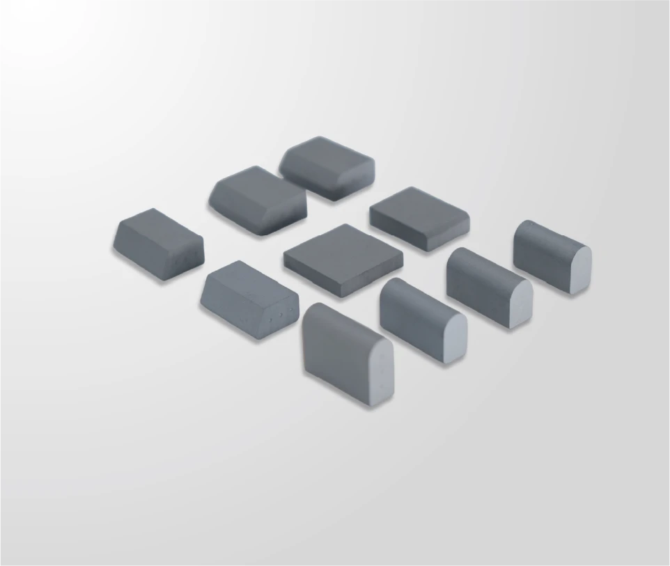
Where an insert is to be used across more than one profile, the grade has to suit the least favourable condition. SENTHAI engineers the hardness and toughness balance against stated service conditions using hardness on the HRA scale together with carbide grain size, and supplies micro grain inserts in trapezoid and bullnose shapes. Where profiles differ in the shock they transmit, a grade chosen for the gentler profile may be inadequate on the harsher one.
Production control is what makes cross-profile use supportable. SENTHAI manufactures in Rayong, Thailand, in a US-invested plant using non-China raw materials, with the full chain in-house from wet grinding and robotic pressing at up to 500 tons through vacuum and low-pressure sintering, automated high-temperature induction brazing and finishing. Because pressing and finishing are controlled in the same facility as the drawing, the tolerance that decides whether an insert fits two different seats can be held consistently between orders.
Material behaviour also changes with the profile’s working conditions. Where an insert is presented at a steeper angle, the leading face carries different stress than at a shallower one, and the failure mode shifts accordingly. Background on cemented carbide in wear applications is published by the International Tungsten Industry Association, and the joining process is described in technical terms by TWI.
Fitment and Tolerance Requirements for Cross-Profile Use
Cross-profile use requires tighter control than single-profile use, because the insert has to satisfy two seats rather than one. SENTHAI works to plus or minus 0.02 mm dimensional tolerances on carbide components and validates fitment against AASHTO and DIN bolt patterns before release, with AASHTO published standards as the reference for agency specifications and DIN covering European and export conventions.
Three checks should be completed before consolidation. Measure both seats and confirm that the insert’s locating features fall within tolerance for each. Confirm the profile angle at which the working face will sit on each blade and whether the resulting contact behaviour is acceptable on the routes involved. And confirm hardware and seated height, since a change in profile changes both. Where any of the three is uncertain, the trial should be run on a small group before the fleet standardises.
A practical safeguard is to keep the verification in writing. A supplier asked to confirm compatibility across two profiles should confirm it against both drawings and state any limitation, such as reduced tolerance margin on one of them. That written confirmation is what a fleet produces if a fitting problem emerges later and the question of who accepted the risk arises.
Evidence to Request With the Insert Compatibility Across Profiles Quote
The evidence list for cross-profile use is the same as for a single profile, applied twice. Ask for dimensional results at the locating features and working face, grade data referenced to a test method such as those published by ASTM, and written fitment confirmation against each seat or pattern involved. SENTHAI inspects and archives every batch, so these records are available on request; the quality control and traceability page describes what they contain.
Where inserts are supplied fitted to a blade, add the joining process description and the inspection applied to the joint, because compatibility across profiles means the joint is loaded differently on each of them. Materials engineering resources published by ASM International help a procurement team assess whether a proposed single grade genuinely covers both applications.

Common Errors in Insert Compatibility Across Profiles and Their Cost
The most common error is assuming that a matching part number means equivalent seats. Part numbers are internal references and describe dimensions, not the seat condition or the angle at which the insert will be presented. The second is consolidating before measuring the seats, which is how a fleet discovers that one group’s blades have worn seats that no correctly made insert will sit in accurately.
The third is standardising on a grade that suits only one of the profiles. Where one application transmits more shock, a grade selected for the gentler one will chip on the other, and the fleet will interpret the result as a quality problem rather than a specification mismatch. The fourth is leaving records mixed. Once a fleet uses one insert across two profiles, a difference in results has two possible sources, and separating them afterwards means reconstructing data that should have been recorded at the time.
The costs appear as fitting problems, higher loss rates on one group and wear records that cannot be interpreted. Measured seats, a written compatibility confirmation and separated records remove all three, and the work involved is a single exercise before the consolidation rather than a continuing investigation after it.
Writing Compatibility Requirements Into a Tender for Insert Compatibility Across Profiles
A tender covering more than one blade profile should state the insert requirement against each. Give the seat or pattern dimensions, the profile angle the working face must suit, the tolerance at the locating features, the grade requirement with its properties, and the retention method. Then require written confirmation of compatibility for each profile rather than a single statement for the order.
Where an equivalent is permitted, define the properties and tolerances it must match on both profiles. Where the programme references published patterns, citing the relevant AASHTO standards keeps offers comparable and gives the receiving inspection a basis for acceptance. One clause is worth adding: require the supplier to state any profile for which the offered insert is not recommended, since a negative answer is more informative than a general assurance.
Insert compatibility across blade profiles is decided by seat geometry, profile angle and tolerance. A part that fits both seats can still present its working face at the wrong angle, and the difference appears later as unexplained wear or loss.
Measure both seats, confirm the angle each profile presents, and require written compatibility confirmation for each. Where a fleet standardises, it should standardise on evidence and keep the records for the two groups separate, because combining them removes the ability to interpret the result.
Send SENTHAI the drawings or seat measurements for each blade profile in the fleet, and the technical team will confirm insert compatibility, tolerance and grade for each application.
Frequently Asked Questions
Can one insert be used across different blade profiles?
It can where the seating features match, the working face sits at an acceptable angle on each profile and the tolerance on both seats allows the insert to seat flat without force. That is a dimensional question answered against drawings rather than against part numbers. Where one of the conditions is not met, keeping the profiles on separate specifications is usually cheaper than adapting the insert.
How do we check seat condition before consolidating inserts?
Measure the seat on a sample of blades from each group, recording depth, surface condition and any deformation, and compare the results with the drawing the insert is produced to. Where seats have worn, an insert that is correctly made will still not seat accurately. Seat condition is the variable most often overlooked in a consolidation decision and the one most likely to produce fitting problems.
Does profile angle change how long an insert lasts?
It changes how the insert is loaded at the surface, so it can change both wear rate and failure mode. A steeper presentation concentrates stress differently from a shallower one, and the insert that performs well on one profile may chip or wear faster on the other. Confirm the angle each profile presents before assuming an insert is interchangeable between them.
What should be recorded when one insert serves two groups?
Keep the wear records separate by profile group, even where the insert part number is shared. Once inserts are used across two profiles, a difference in result has two possible sources, and separating them afterwards requires reconstructing data that should have been recorded at the time. Position, measured wear and renewal cause should be recorded per group and per blade.
Related articles
 Carbide Insert Spares Planning: Holding the Right QuantityCarbide InsertsCarbide Insert Tender Specification: Writing Requirements That HoldCarbide Inserts
 Insert Cost Per Metre of Cutting Edge: The Inputs ExplainedCarbide InsertsCarbide Insert Inspection: Checking a Delivery Before FittingCarbide Inserts