
Dimensional Tolerances for Wear Parts: Which Ones Actually Matter
A tolerance that nobody measures is a tolerance that does not exist, and a tolerance that is tighter than the job needs is a cost with no benefit. Wear parts tolerances sit in the…
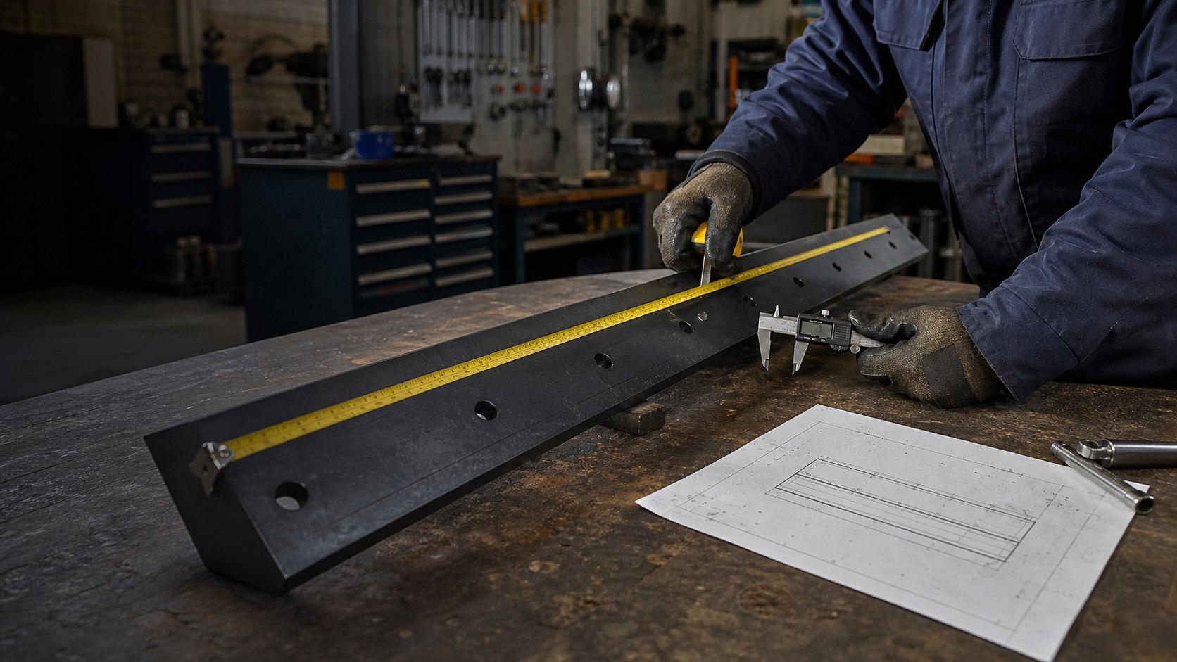
A tolerance that nobody measures is a tolerance that does not exist, and a tolerance that is tighter than the job needs is a cost with no benefit. Wear parts tolerances sit in the middle of that tension: too loose and the part will not bolt on or will wear unevenly, too tight and the price carries inspection and rework that change nothing in service. Sorting the difference is mostly a matter of knowing which dimension does what.
Three families of tolerance decide a wear part. Fitment tolerances govern whether it mounts, form tolerances govern how it seats and wears across its length, and the thickness allowance governs how long it lasts. Each is verified differently and each has a different cost consequence when it is wrong.
The Mechanism, Stated Plainly
A tolerance is the permitted range around a nominal dimension, and it exists because no manufacturing process produces one exact size. What matters for a buyer is that a tolerance is only meaningful when it is attached to a dimension that has a function. Without that link it becomes a number copied from another drawing.
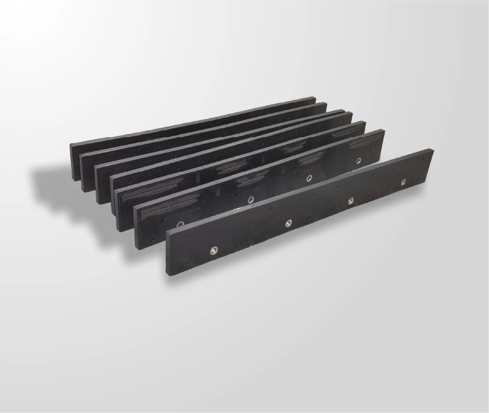
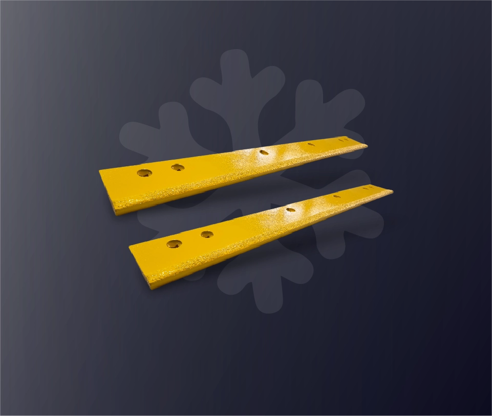
The fitment family covers the features that locate the part: hole pattern, hole diameter, countersink angle and the section shape that mates with the mounting surface. These tolerances are absolute in effect, because a hole in the wrong place cannot be argued with. Definition and terminology for dimensional specification and verification rest on published standards, which is why material and test standards such as those issued through ASTM appear in nearly every edge specification.
The form family covers flatness, straightness and camber. These do not stop a part mounting, so they are often left out, and their absence shows up as a part that rocks on the moldboard, loads a few bolts instead of all of them and wears to a bow rather than evenly.
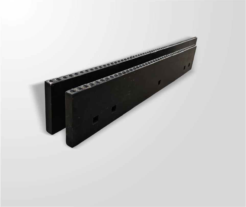
The third family is thickness, and it behaves differently again. A thickness tolerance is not only a manufacturing limit; it is the wear allowance the part starts with, and it interacts with countersink depth at the bolt line, which is where an over-thin edge fails.
Hole Position, Spacing and Fitment
Hole position is the tolerance that most often decides whether a delivery is usable. It should be dimensioned from a datum — normally one end of the part or the first hole in the line — rather than as a chain of dimensions from hole to hole, because a chain accumulates the error of every measurement in the sequence.
Spacing matters as much as position. A pattern in which the pitch is close but the line is straight is far easier to bolt up than one with a correct total length and uneven spacing, since the second cannot be corrected with a drift punch and a little patience. Hole diameter and countersink angle have to suit the fastener: a plow bolt needs its countersink to match, or the head will sit proud and wear flat before the edge does.
Bolt patterns in highway maintenance work are commonly described against published pattern standards, for example the material and edge specifications distributed through the AASHTO publications store, and machine and attachment interfaces follow the conventions published in the SAE standards programme. Naming the pattern from a standard is quicker and less ambiguous than describing it in prose.
One further dimension belongs in this family: the distance from the hole line to the working edge. It sets how much material remains around the countersink and how the part behaves as it wears, so it should be called out on the drawing rather than inferred from the overall length.
Flatness, Straightness and Camber
Flatness is the tolerance most often omitted and most often regretted. A cutting edge that bows across its length contacts the surface over part of its span and transfers load into the bolts nearest that contact, so the same part wears unevenly and the bolt line fatigues where the load concentrates.
Straightness and camber describe related but distinct conditions. Straightness applies along the length of a section that should be linear; camber describes a deliberate or permitted curvature across the width, which matters where the part has to follow a moldboard arc or seat against a curved mounting surface.
The practical question is how much form error the application tolerates, and it is answered by the mounting surface rather than by the drawing. A part that seats on a machined face needs a tighter flatness allowance than one that seats on a rolled moldboard with a rubber layer taking up variation. Verification is straightforward either way — a straight edge and a feeler gauge at defined points, recorded on the inspection sheet.
Where a European standard is named in the specification, the tolerance and verification clauses are usually written against standards indexed through the national and European bodies listed at DIN, which is the practical reference for a programme that supplies both North American and European equipment.
Thickness and Wear Allowance
Thickness is the tolerance that decides service life, and it is also the one most likely to be specified from habit. The nominal thickness sets both the load the part can take and the material available to be worn away, and the minimum permitted thickness is what determines when the part must be replaced.
The relationship with the bolt line is the part that gets overlooked. Countersinking removes material around each hole, so the effective section at the bolt line is thinner than the nominal thickness, and the point at which the surrounding metal starts to yield is set by that reduced section rather than by the plate as a whole. A tolerance that allows thickness to run to the low end without a corresponding check at the countersink buys less service than the nominal figure suggests.
Material choice and thickness should be considered together rather than in sequence, because they trade against each other. The wear and materials literature catalogued by ASM International is a reasonable starting point for that comparison, and it is more useful than a single hardness figure when the choice is between a thinner abrasion-resistant section and a thicker conventional one.
The drawing should state the thickness with a tolerance, name the wear limit if the part is renewable, and specify whether the dimension is measured on the flat or at the section. Ambiguity here is measured in months of service.
How Tolerance Is Verified and Reported
Measured against a datum, recorded per feature.
Each called-out tolerance is measured against its stated datum with an instrument suited to the magnitude, and the values are written onto the inspection record for that lot rather than summarised as a pass.
The instrument follows the tolerance. Calipers and micrometers cover thickness and section; a height gauge or a coordinate measuring routine covers hole position from a datum; go and no-go gauges cover hole diameter quickly. What matters is that the method is agreed in advance and that the record shows nominal, tolerance and measured value, so a question about one shipment can be answered without re-measuring the part.
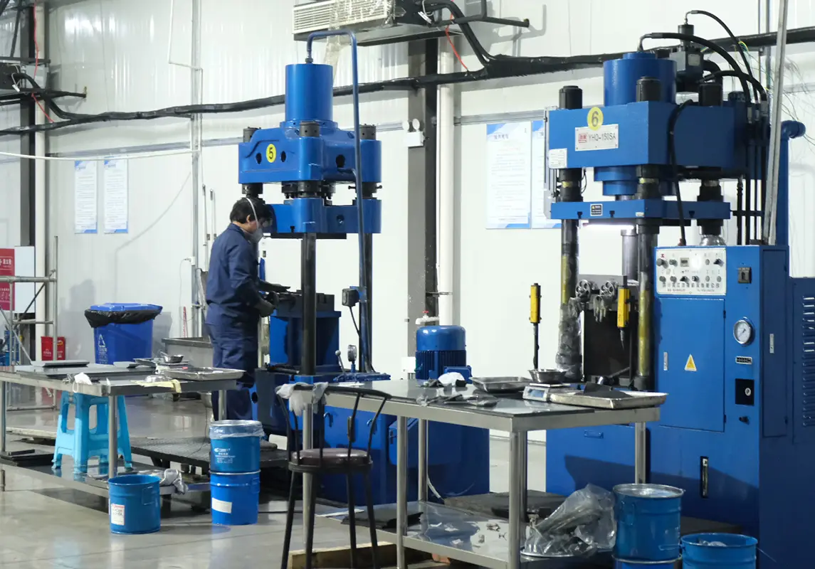
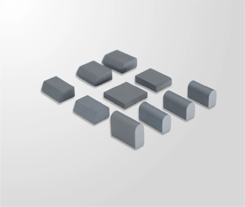
Sampling or full inspection is a decision per feature. Fitment features that would stop the part mounting are usually worth checking on every piece; thickness and form are commonly sampled. SENTHAI holds machine insert pockets to a tolerance of ±0.02 mm, which is the class of feature where the cost of full inspection is justified, and validates AASHTO and DIN bolt patterns against the customer drawing or a physical sample. Lot-level traceability means every batch is inspected and archived.
Measurement itself has to be trustworthy, which is the point of the national metrology infrastructure described by NIST. A shop-floor gauge that has never been checked against a reference is a plausible source of an argument rather than a resolution of one.
Over-Specifying and Its Cost
Tolerance has a price and the price is not linear. Halving a permitted deviation typically adds inspection time, increases scrap and rework, may require a different machining or grinding operation, and slows the process down. On a part that is going to lose a millimetre of material in its first season, that cost buys nothing.
The waste is usually found in three places: a tight tolerance on a cosmetic or marking dimension, a tight tolerance on a feature that the process cannot hold reliably, and a tight tolerance on a dimension that nobody measures. The third is the worst of them, because it makes the drawing harder to satisfy without making the part any better.
There is also an operational cost that shows up later. A tolerance tighter than the manufacturing process can hold on a good day produces either a rejected delivery or a stream of deviations, and a programme running on concessions is a programme with no real specification. Matching the callout to the process that will make the part is part of specifying it well.
The test is simple and worth applying to every dimension: if this measurement came back at the limit of its tolerance, what would change in fitment, wear or service life? If the answer is nothing, the dimension does not need the tolerance.
Tolerances to Fix in the Drawing
A short list covers most wear part drawings. Fix the hole pattern and its pitch against a datum, including hole diameter and countersink angle to suit the fastener. Fix the distance from the hole line to the working edge, since it governs the remaining section. Fix flatness or camber across the mounting face to suit the surface the part seats on, and fix thickness with an explicit tolerance and a wear limit where the part is renewable.
Everything else can be covered by a general tolerance note, which keeps the drawing readable and keeps the inspection effort where it matters. Then give the drawing a revision number and change it when something changes, so the tolerance and the part stay in step.
Before releasing, compare the callouts against the process that will produce the part: whether the pocket machining, the pressing or the finishing operation can hold each figure repeatably. A tolerance that is right in principle and unreachable in production is a specification that produces a dispute, and the place to settle it is the drawing review rather than the goods-in inspection.
Tolerance on a wear part is a design decision with a cost attached, not a quality statement. Fitment tolerances — hole pattern, countersink and section — are absolute because a part that does not mount is of no use. Form tolerances for flatness and camber decide how evenly the part wears and how the load is shared across the bolts. Thickness governs both wear allowance and the strength remaining at the countersink. Fix those deliberately, verify them against a datum with a recorded method, and leave the rest to a general note; the savings show up in price and in fewer arguments at goods-in.
Send SENTHAI the drawing or the mounting details and the service conditions, and the technical team will review the tolerance callouts, flag any that carry cost without benefit and confirm what the process can hold.
Frequently Asked Questions
What is a reasonable tolerance for a wear part?
It depends on what the dimension does. Features that locate the part, such as hole pattern, hole diameter and countersink angle, need tolerances tight enough that the part mounts reliably. Flatness and camber need only enough to seat and wear evenly, and thickness needs a tolerance that preserves the wear allowance and the section remaining at the bolt line. A dimension with no effect on fitment, wear or life does not need a tight tolerance at all.
What is the difference between limits, fits and tolerances?
A tolerance is the permitted range around a nominal dimension, expressed as a plus and minus band or as upper and lower limits. Limits are that range written as two absolute size values rather than as deviations. A fit describes the relationship between two mating dimensions, for example a hole and a fastener, which is what determines whether the assembly goes together with clearance or interference. Wear part drawings mostly use tolerances and limits, with fit implied by the fastener.
Which tolerances should appear on a cutting edge drawing?
The hole pattern with pitch, hole diameter and countersink angle referenced to a datum; the distance from the hole line to the working edge; flatness or camber across the mounting face; and the section thickness with its tolerance, plus a wear limit if the part is designed to be renewed. A general tolerance note covers everything else, which keeps the drawing readable and concentrates inspection on the features that decide whether the part mounts and how it wears.
Does a tighter tolerance change price and lead time?
It can change both. Tighter callouts usually add inspection time, may add scrap or rework, and can require an extra machining or grinding step, which affects the order quantity that makes the work economic. The effect appears in the quotation rather than in a rule of thumb, and the applicable price, quantity and schedule terms are stated in the written quotation or order documents.
Related articles
 Developing a Custom Blade Profile: Field Data to DrawingCustom/OEM and private-label manufacturing
 Tooling, Lead Time and Changeover for Custom Wear PartsCustom/OEM and private-label manufacturing
 Sampling a Wear Part Order: First Article, Pilot and ProductionCustom/OEM and private-label manufacturing
 Reverse Engineering a Worn Part: Measuring and Documenting ItCustom/OEM and private-label manufacturing