
Reverse Engineering a Worn Part: Measuring and Documenting It
A worn part on a bench and no drawing in the file is the ordinary starting position for a reproduction order. Reverse engineering wear parts begins with that sample, but the sample is a…
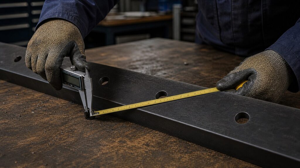
A worn part on a bench and no drawing in the file is the ordinary starting position for a reproduction order. Reverse engineering wear parts begins with that sample, but the sample is a record of wear rather than of design: the surfaces that moved material away are exactly the surfaces that no longer carry the original dimension. Every measurement taken from them is partly a measurement of what went wrong.
That is not an argument against using the sample. It is an argument for treating it as one input among several and for recording the reconstruction, so the reproduced part can be checked against something other than a worn original. What follows covers where measurement fails, how original geometry is recovered, what has to be documented alongside it, and what a supplier needs to begin.
Why Measuring a Worn Part Fails
Worn surfaces are not the design surface.
Measuring a worn part records the wear pattern rather than the drawing, so a direct copy reproduces the deformity. The useful measurements come from the features that survived service, such as the hole line and the mounting face.
Wear is not evenly distributed. On a ground-engaging edge the tip loses millimetres while the bolt line loses almost nothing, so a dimension taken at the worn face and a dimension taken at the hole line describe two different things. Scaling a thickness up from a partly worn section is a guess dressed as a measurement.
Deformation compounds the problem. Edges bend, fastener heads mushroom, insert pockets crater and section thickness varies along a length that was originally uniform. A copy of that geometry starts life halfway through its service life, and the error is invisible until the part is on the machine.
Metrology is only useful when the reference itself is sound, which is the principle behind the measurement infrastructure described by NIST. The practical rule for a worn part is to measure what survived and to infer the rest from the mating component and from the wear pattern itself.
Establishing the Original Geometry
The reconstruction starts with the features that did not move. Hole centres and pitch, countersink angle, the mounting face and any end section that never engaged material are the anchors, because service does not change them. Their measurements can be transferred directly into the new drawing.
Thickness needs more care. The right approach is to find the original surface rather than the worn one, using a witness line where the unworn section meets the worn area, the least-worn section of the part, or a mating component that constrains the geometry. On a symmetric part, the end that saw less wear often gives a usable section to mirror across the centreline.
Where more than one worn sample is available, measuring both is worth the effort. Two parts that saw different service will show different wear patterns, and the features that agree across both are the ones closest to the original design. Where only one sample exists, photographs taken straight on and from the side with a scale in frame preserve information that a handful of caliper readings will not.
Three-dimensional scanning helps with profiled and free-form surfaces, but only as a starting point. A scan of a worn part is a scan of a worn part; the model has to be fitted back to design intent by straightening the uniform sections, restoring the tip profile and removing service deformation. A reconstruction that is not documented will be measured against the wrong reference on the next order.
Tolerances, Reference Surfaces and Datums
A reconstructed drawing needs a datum scheme, and the datums have to be chosen from features that survived. On a blade or cutting edge the bolt line is normally the primary datum, with hole pitch and the section profile referenced from it. Dimensioning from a worn face instead produces a drawing that cannot be inspected on a new part and cannot be compared with the original sample.
Three requirements carry most of the fitment risk: hole position referenced to a datum, flatness or camber where the part seats against a moldboard, and thickness where a wear allowance has to be preserved. Test methods for those checks, and the way hardness is quoted, follow published standards such as those issued through ASTM, which is what makes a tolerance callout enforceable rather than conversational.
The datums and the tolerance should be written into the drawing before the first part is made, not agreed verbally during a fitment trial. A verbal agreement disappears with the people who made it, and the next order then begins from ambiguity.
Documenting Material and Heat Treatment
Geometry is half a reproduction. Material and treatment are the other half, and a worn part rarely carries a legible grade mark. Where documentation exists, use it; where it does not, the material can be identified by family from a hardness reading on a defined scale together with an indication of grain size, and the result should be recorded as a band rather than a single figure.
For brazed or welded assemblies, the joint matters as much as the carbide. Joint design, filler metal family and any post-join heat treatment belong on the record, and welding practice is documented by the technical literature of organisations such as the American Welding Society. Where a part has been field repaired, the repair has to be recognised and excluded from the design intent.

Reproducing the process route matters because grade and route are inseparable. Powder preparation, pressing, sintering and any joining step all affect the properties the part delivers, and the powder metallurgy route is described in the technical material published by the Metal Powder Industries Federation. Grade data published by carbide producers, for example the references maintained by Hyperion Materials & Technologies, is what allows a band to be quoted in the drawing rather than a trade name.
First Article and Fitment Verification
A reconstruction is a hypothesis until a first article proves it. The check has two halves: dimensional inspection against the reconstructed drawing, and a physical fitment test on the machine, the moldboard or a mating plate. Both halves matter, because a part can pass every dimension and still foul the assembly.
Record the measured values, keep the approved first article and hold the original worn sample beside it. The sample is not a reference dimension, but it is a useful check on orientation, edge position and the shape of the working face, and it is the only physical record of what the part did.
Where the part is one of a family, verify the interface once and the working face per variant. Hole pattern, section and mounting face are shared properties; the insert profile and tip geometry are not. Establishing which features the family holds in common reduces both the reconstruction work and the inspection load on every later order.
The verification should also confirm the interface conventions the machine uses. Machine and attachment interfaces follow the published standards programme of the SAE, and bolt patterns used in highway maintenance work are commonly described against the pattern standards published through AASHTO.
Cost and Time Involved
The effort in a reconstruction is driven by how much geometry is undocumented rather than by the size of the part. A part with an available drawing, an intact pattern and a known grade takes far less work than one where the section, the profile and the material all have to be inferred from a worn sample.
Four factors raise the work: the number of features that cannot be measured directly, whether new tooling or fixturing is required, whether a physical trial is needed to confirm fitment, and how many variants of the same part are in the programme. A household of related parts sharing one interface is usually cheaper per part than a single unique one, because the reconstruction work is shared.
The applicable cost, quantity and schedule terms are stated in the written quotation or order documents. What a buyer can control before that is the completeness of the input: a mating component, a second sample with a different wear pattern, and any historical paperwork all reduce the engineering assumed into the price.
What the Supplier Needs From You
The sample, its mating part and the service data.
Send the worn sample, the mating component or interface data, any drawing or old paperwork, the service conditions and a note on how many parts failed the same way, so the reconstruction starts from evidence rather than assumption.
The mating component is the most valuable single item and the most often omitted. It constrains the interface, shows how the part located in service and often reveals the original section where the worn part cannot. Where the mating part cannot be shipped, a measured sketch of the mounting face and hole pattern is the next most workable option.
Service data changes the reconstruction rather than the geometry. The material the part worked in, the machine it was fitted to and the failure mode tell a supplier whether the original design was correct or whether the replacement should differ. A reproduction of a part that failed early is a chance to improve the specification at the same time, and the choice between faithful reproduction and a specification change should be an explicit decision recorded with the order.
A worn part can be reproduced reliably, but only if the worn surfaces are treated as evidence rather than as dimensions. The surviving features — hole pattern, countersink, mounting face and unworn sections — anchor the reconstruction; the mating component constrains it; and a documented grade and process route make the result repeatable rather than a one-off. The drawing produced in the process becomes the controlled document for every later order, which is the point at which a one-off replacement turns into a supply programme.
Send SENTHAI the worn sample, the mating component or a measured sketch of the interface, and the service conditions, and the technical team will work through the geometry, the grade and a fitment check before quoting.
Frequently Asked Questions
What does reverse engineering mean for a wear part?
It means reconstructing the original design intent of a part from a physical sample, because no drawing exists or the drawing no longer matches the part. The work combines measurement of the features that survived service, inspection of the mating component and documentation of the material and process route. The output is a controlled drawing that can be quoted, produced and inspected, which is what turns a single replacement into a repeatable order.
Can a worn part simply be 3D scanned and copied?
A scan is a useful starting point but not a finished definition, because it captures the worn surface with its deformation, edge loss and any field repair. The scanned model has to be fitted back to design intent: uniform sections restored, the worn profile rebuilt to the original section and the interface referenced to surviving features. A scan used without that step reproduces the wear pattern as if it were the design.
Is the original drawing needed to reproduce a discontinued part?
It helps more than anything else, because it removes the inference from the job, but it is not essential. Where no drawing exists, a measured sample plus the mating component and any historical paperwork is enough to reconstruct the geometry, and the resulting drawing becomes the reference for later orders. Where a drawing does exist, the part should still be measured, since drawings and fielded parts often differ.
How long does reversing a wear part take, and what does it cost?
The work is driven by how much geometry has to be inferred rather than by part size: how many features cannot be measured directly, whether tooling is needed, whether a fitment trial is required and how many variants share the interface. A complete input package shortens both the engineering and the lead time. The applicable cost, quantity and schedule terms are stated in the written quotation or order documents.
Related articles
 Developing a Custom Blade Profile: Field Data to DrawingCustom/OEM and private-label manufacturing
 Tooling, Lead Time and Changeover for Custom Wear PartsCustom/OEM and private-label manufacturing
 Dimensional Tolerances for Wear Parts: Which Ones Actually MatterCustom/OEM and private-label manufacturing
 Sampling a Wear Part Order: First Article, Pilot and ProductionCustom/OEM and private-label manufacturing