
Developing a Custom Blade Profile: Field Data to Drawing
Nobody sets out to design a blade profile. A programme develops one because a part keeps failing in a specific way on a specific surface, and the failure points at a shape rather than…

Nobody sets out to design a blade profile. A programme develops one because a part keeps failing in a specific way on a specific surface, and the failure points at a shape rather than a material. Developing a custom blade profile starts from that evidence: what the edge did, where it wore, and what the operator could not do with it.
The mistake to avoid is treating the exercise as drawing work. A profile that looks right on a screen and has never been related to the material being moved, the machine pushing it and the way the operator runs it is a shape rather than a design. The route that works runs from failure to field data to geometry to a trial, and each step constrains the next.
Start With the Failure, Not the Drawing
Most profile projects begin with a complaint that can be translated into geometry. An edge that rounds off and stops cutting and one that keeps cutting but packs material in front of the moldboard are different failures, and they call for different changes to the attack angle, the tip profile and the insert layout.
Four failure patterns cover a large part of the field. Edge rounding, where the edge polishes instead of cutting, points towards a harder or more abrasion-resistant working face, or towards a sharper entry. Packing, where material builds in front of the blade, often points towards the attack angle and the relief behind the edge rather than the tip itself. Insert loss points at the fixing method and the pocket. Chatter or an uneven cut across the width is usually a form problem rather than a profile problem, and it belongs to flatness and camber rather than to geometry.
Service conditions decide which of those matters most. Unpaved roads and gravel surfaces wear an edge differently from paved surfaces and packed snow, and road programme guidance such as that published by the Federal Highway Administration treats surface type as a primary maintenance variable for exactly that reason. Recording which surface a part worked on is the cheapest piece of field data available and the most often skipped.
Field Data Worth Collecting
A useful data set is small and specific. For each machine, record the material worked, the surface type, the approximate hours per season, the wear pattern and its location on the blade, and the remaining section measured at a defined point such as the bolt line. Photographs with a scale in frame, taken straight on and from the side, carry information that notes rarely capture.
Operator input belongs in the same file. The useful questions are behavioural rather than technical: what had to be done differently with this blade, how many passes a road took, whether the machine pushed harder than usual, whether the blade had to be run at an angle. Those answers often explain a wear pattern that looks like a material problem.
Two or three machines of the same type working different surfaces make a far better basis than one machine working one surface, because they separate the effect of the blade from the effect of the site. Research published through the Transportation Research Board consistently shows that measured service conditions, rather than nominal ones, are what make a comparison defensible later.
Turning Measurements Into a Profile
Geometry has a limited number of variables that can be changed one at a time: the attack or rake angle of the edge, the tip radius or the flat that replaces it, the number and pitch of inserts, the insert profile itself, and the relief angle behind the cutting face. Changing several at once produces a result nobody can interpret, which is the commonest reason a profile project runs for three iterations instead of one.
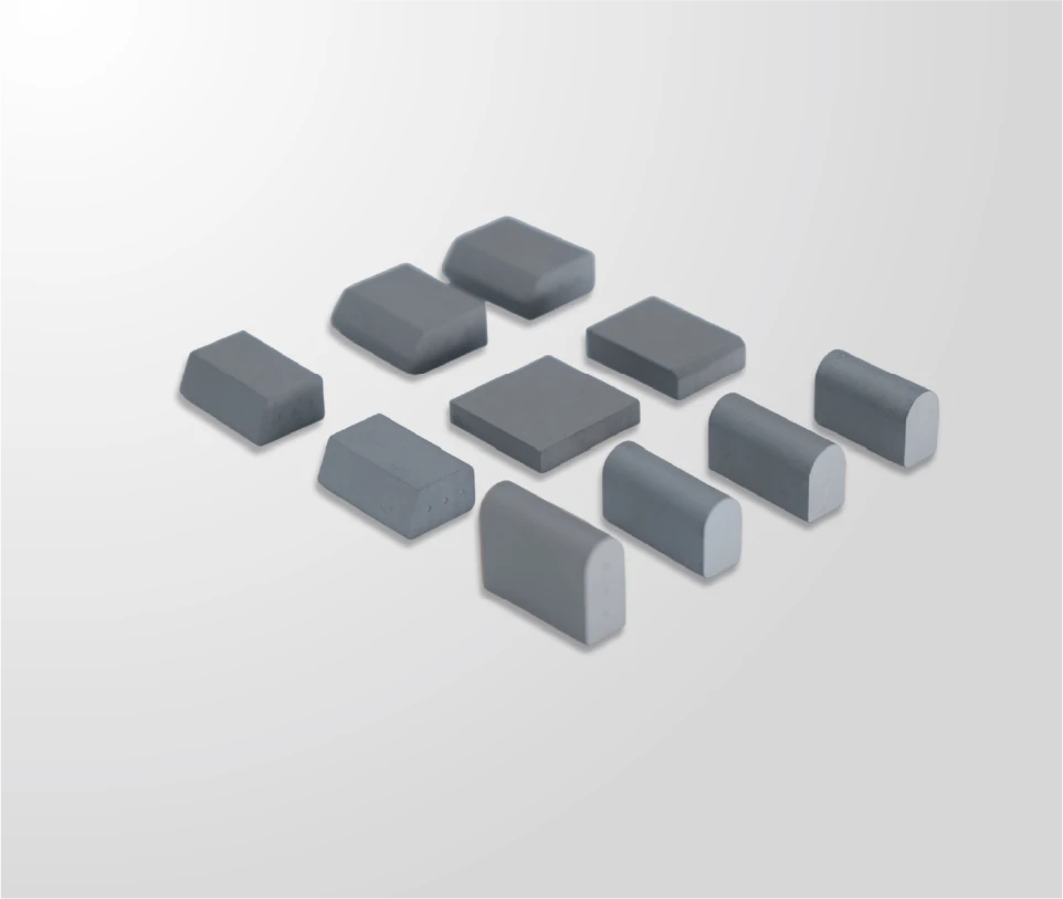
Insert profile is the variable with the widest effect. Trapezoid and bullnose profiles distribute load and cutting action differently, and the choice interacts with the pitch: wider spacing with a larger insert behaves differently from closely spaced small ones on the same body. Insert geometry references published by carbide producers are a sensible starting point before any prototype is made, because they describe what the shapes do rather than what they look like.
Material response should be built into the model early rather than discovered in the field. Wear-resistant steel performance data published by producers such as SSAB gives a basis for comparing sections, and the wear and materials literature catalogued by ASM International covers the mechanisms — abrasion, impact, adhesion — that decide which of the candidate designs is likely to work.
The output of this stage should be a drawing with a revision number and a note explaining what each element is intended to achieve. A profile without that note is very hard to iterate on, because nobody can tell which feature was a decision and which was a leftover.
Material and Fixing Decisions
Material selection for a blade profile is a balance rather than a ranking of grades. Harder grades resist abrasion and are more prone to chipping under impact; tougher grades survive impact and wear away faster. Grain size in the carbide moves the balance as much as the hardness figure, which is why a grade is properly specified as a combination rather than as a single number.
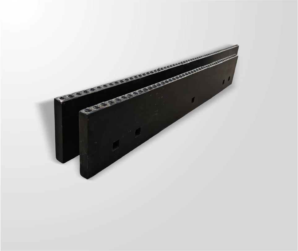
Fixing is the other half of the design. Brazed inserts give a continuous cutting edge and a fixed working face; replaceable inserts allow a worn portion to be renewed without scrapping the body; a full-face attachment suits a flexible blade where the body has to deform rather than resist. Peer-reviewed work in journals indexed through MDPI is a useful source when the mechanism being addressed is wear rather than impact, and it is often more specific about test conditions than a product datasheet will be.
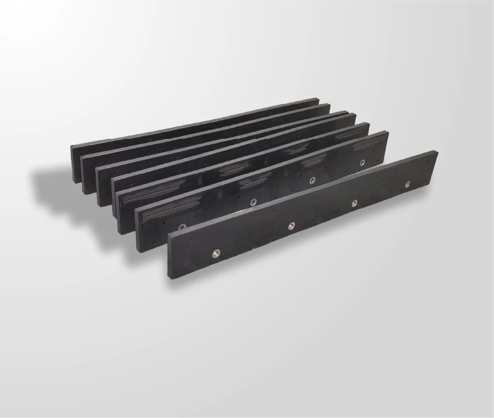
Where the profile is being developed for a flexible or rubber-backed system, the body, the layer and the edge have to be designed together. SENTHAI develops application-specific systems of this kind, and the engineering steps behind a custom rubber-flex snow plow blade are a reasonable model of how the sequence runs when the blade has to deform rather than cut rigidly.
Prototyping and Field Trial Design
A prototype batch is small by definition, and its purpose is to answer questions rather than to supply a season. Before it is made, write down what would count as success in measurable terms: remaining thickness at the bolt line after a defined number of hours, absence of insert loss, no packing in front of the moldboard, or a reduction in passes to bring a road back to grade.
Run the trial against a baseline. That means the same machine, the same road type and the same period as an existing profile where possible, because an uncomparable trial produces an opinion rather than a result. If a direct baseline is impossible, record enough of the difference to be explicit about what the comparison is not.

Retain the trial parts. A worn prototype measured at the end of the trial, kept beside a worn baseline part, is evidence; a written summary of what the operator thought is context. Both are worth having, and neither substitutes for the other.
Iteration, Cost and Timing
Iteration is normal and predictable, and its cost is dominated by how many variables were changed at once. A programme that adjusts one geometric variable per trial usually converges in fewer rounds than one that redesigns the whole profile each time, even though each individual round feels slower.
Cost and timing follow the same logic as any custom part. New geometry may need new forms, new pocket tooling or new fixtures; each trial consumes production slots; and each trial needs a period in service before its result means anything. That last item is the one that cannot be compressed, and it is the reason a profile developed in spring gets tested in the following winter rather than the current one.
The applicable cost, quantity and schedule terms are stated in the written quotation or order documents. What the buyer controls is the quality of the input and the discipline of the trial, and both shorten the project more than any supplier-side measure.
Handover to Production
The end of a profile project is a frozen drawing rather than an agreed shape. That means a revision number, the tolerances that matter written onto it, the grade and the fixing method stated, the tooling identified and the first article approved against the drawing rather than against a prototype.
Handover should also capture the intent. A short note recording why the attack angle, the insert pitch and the profile were chosen preserves the reasoning when somebody asks for a change in two seasons’ time, and it makes the answer to that request a design decision instead of an argument about preference.
Keep the records together afterwards: the approved first article, a reference sample, the trial results and the drawing revision. That file is what allows a repeat order to be placed on the same basis as the original, and what allows the profile to be improved deliberately rather than accidentally.
A custom blade profile is designed from the failure outwards. The failure mode and the surface worked on point to which of the few geometric variables should move: attack angle, tip profile, insert form and pitch, or the fixing method. One variable at a time, a trial with a defined end point and a baseline to compare against, and a frozen drawing with the reasoning recorded are what turn a prototype into a repeatable part. Material and fixing choices belong in the same discussion as geometry, because they trade against each other in service.
Send SENTHAI the failure pattern, the surface types and any photographs or measurements from the field, and the technical team will work through the profile options, the grade balance and a trial design before quoting.
Frequently Asked Questions
How do you design a cutting edge from a failure, not a drawing?
You start by translating the failure into geometry. Edge rounding, material packing in front of the moldboard, insert loss and chatter each point at a different variable: the working face and entry angle, the attack angle and relief, the fixing method, or the form of the body. Service conditions then decide which matters, because abrasion and impact call for opposite changes in hardness and toughness balance.
What field data is worth collecting for a blade profile?
Per machine: the material and surface type worked, seasonal hours, where the wear occurred, the remaining section measured at a defined point such as the bolt line, and photographs with a scale in frame. Add the operator’s account of what had to be done differently. Two or three machines of the same type working different surfaces produce a far better basis than a single machine, because they separate the blade from the site.
Should a custom profile use brazed or replaceable inserts?
It depends on what the blade has to do. Brazed inserts give a continuous cutting edge and a fixed working face, which suits abrasive duty where edge integrity matters most. Replaceable inserts allow a worn portion to be renewed without scrapping the body, which suits programmes that want a lower long-run material cost. Where the blade has to deform, as in a rubber-backed system, the body and the layer have to be designed with the edge.
How many iterations does a profile project need, and what does it cost?
Fewer iterations come from changing one geometric variable per trial rather than redesigning everything at once, so the discipline of the trial matters more than the number of rounds. Cost and schedule depend on whether new forms, pocket tooling or fixtures are needed and on how long each trial must run in service. The applicable cost, quantity and schedule terms are stated in the written quotation or order documents.
Related articles
 Tooling, Lead Time and Changeover for Custom Wear PartsCustom/OEM and private-label manufacturing
 Dimensional Tolerances for Wear Parts: Which Ones Actually MatterCustom/OEM and private-label manufacturing
 Sampling a Wear Part Order: First Article, Pilot and ProductionCustom/OEM and private-label manufacturing
 Reverse Engineering a Worn Part: Measuring and Documenting ItCustom/OEM and private-label manufacturing