
Isolated Carbide Inserts: Stopping Lateral Cracks Before They Start
A crack in one carbide insert should not be the end of a blade section, but in a continuous-edge design it often is. The crack travels from insert to insert, splitting the row and…
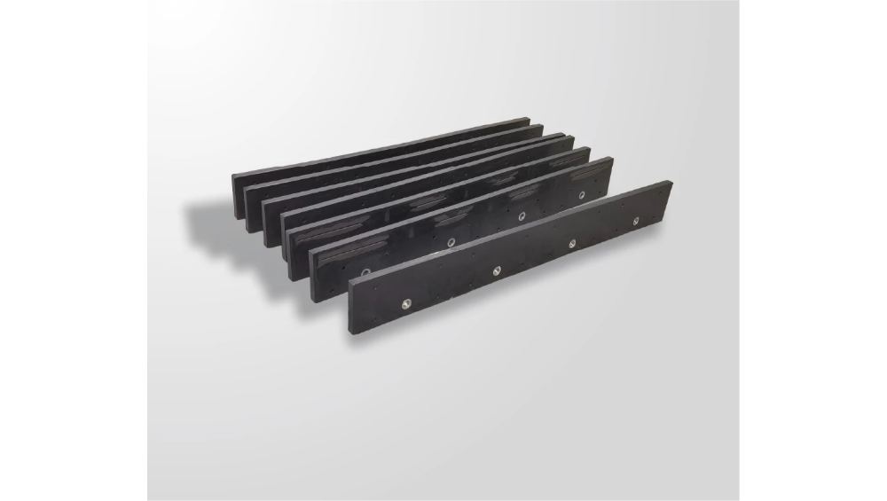
A crack in one carbide insert should not be the end of a blade section, but in a continuous-edge design it often is. The crack travels from insert to insert, splitting the row and taking the whole cutting edge out of service. The isolated insert design breaks that path: each insert works as its own unit, so a crack in one does not become a crack in all.
This article explains the mechanics of lateral cracking, why isolated inserts stop the path, what the design does for structural integrity under repeated impact, and how to verify the design in practice.
Cracks travel unless design stops them
Carbide is hard, and hardness comes with a price: cracks can propagate. In a blade where inserts are arranged in a continuous row or share a common structure, a crack that starts in one insert has a path to the next, and the failure spreads along the edge.
The spread is the expensive part. One cracked insert is a maintenance item; a cracked row is a blade replacement, and the replacement happens at the moment the edge is needed most. The design question is whether the geometry and the layout give the crack a path or stop it.
The isolated insert design is an answer to that question: by separating the inserts, the design removes the path. Each insert absorbs its own impact and fails on its own terms, and the rest of the edge keeps working.
How do lateral cracks start and spread?
Lateral cracks start where the impact concentrates. A manhole cover, a curb head, a frozen ridge, or a buried object delivers a sharp load to one point on the edge, and the carbide at that point takes the energy it cannot absorb.
The crack starts at the impact zone and then propagates. In a continuous arrangement, the crack follows the material to the neighboring insert, widening as it goes. In a segmented or isolated arrangement, the crack runs until it meets the boundary between units, and the boundary is where it stops.
The propagation also depends on the carbide grade and the residual stress state. A grade with high toughness resists crack initiation; a well-relieved process reduces the internal stress that drives propagation. SENTHAI describes its inserts as produced with processes that minimize internal stress, which reduces the risk of micro-cracking during brazing and field use.
Why isolated inserts break the path
The isolated insert design breaks the crack path in two ways.
First, the physical separation: each insert is a distinct unit, so the crack has no continuous material to travel through. The impact zone is contained, and the neighboring inserts are untouched.
Second, the load distribution: because the inserts are isolated, an impact on one insert does not transfer the full load to the row. The surrounding structure absorbs part of the energy, and the insert takes only its share.
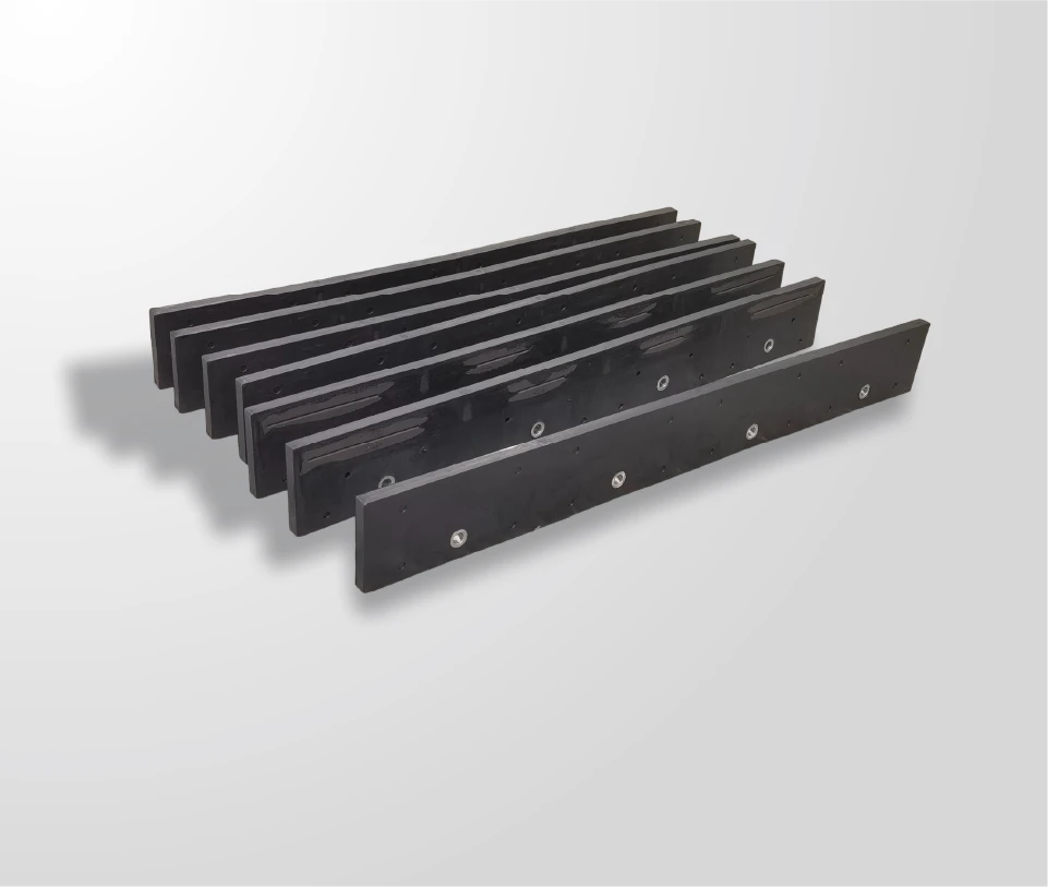
SENTHAI describes the isolated insert design in its packed ice carbide kit as preventing lateral cracking and ensuring maximum structural integrity, with the inserts strategically isolated from one another for enhanced ice penetration. The description is the design intent; the verification is what proves it holds.
Structural integrity under repeated hits
Winter duty is not one impact; it is a season of impacts, and the design has to hold under repetition. The isolated layout’s value compounds over time: each hit is contained, each insert fails on its own terms, and the edge as a whole keeps its structure.
The structural benefit also extends to the maintenance plan. A blade with isolated inserts can lose an insert and keep working, giving the fleet a window to schedule the repair instead of an emergency changeout. The inspection finds the damaged insert, and the section continues until the planned maintenance window.
That is the practical difference between a design that fails gracefully and one that fails all at once. The isolated layout is engineered for the graceful version.
The graceful failure also matters for the economics. A section that loses one insert but keeps working can be scheduled for a planned repair at the shop, while a section that loses its whole row is an emergency changeout in the field. The difference in cost is the difference between a maintenance event and a service failure, and it is one of the strongest arguments for the isolated layout on impact-heavy routes.
The verification of the design should also cover the long season, not just a single event. An insert that survives one impact proves little; one that survives a winter of impacts, inspected at intervals, proves the layout holds under repetition. The field trial should therefore run through a defined number of passes with inspections at checkpoints, so the design’s structural integrity is demonstrated over time rather than assumed from one good result.
The same verification logic applies across the fleet’s blade types. The isolated layout is one construction among several, and the comparison against a continuous-edge blade on the same route is what shows whether the isolation is earning its place. The fleet that tests both constructions side by side gets a decision based on damage patterns, not on brochure descriptions.
The damage patterns, recorded over the trial, are the evidence the next specification is built on.
The evidence, not the brochure, decides the construction.
The trial is the proof, and the proof is the purchase.
The purchase follows the evidence, and the evidence is measured.
Measure it again next season.
And the season after.
The graceful failure also matters for the economics. A section that loses one insert but keeps working can be scheduled for a planned repair at the shop, while a section that loses its whole row is an emergency changeout in the field. The difference in cost is the difference between a maintenance event and a service failure, and it is one of the strongest arguments for the isolated layout on impact-heavy routes.
Each isolated insert is brazed as its own unit, so the surface preparation and the brazing control apply per insert rather than across a row. The inspection should check the individual bonds, and the batch records should cover each insert’s production.
How do you verify the design in practice?
The design claims should be verified the way any blade claim is: with samples and field data.
| Field check | What it confirms |
|---|---|
| Run a sample on an impact-heavy route | Real-duty behavior over a defined number of passes |
| Check whether damage stays contained | The isolation works in the field |
| Compare with a continuous-edge blade | The failure-pattern difference on the same route |
| Review the batch records | The sample’s construction is tied to a production run |
| Ask for the conditions behind the claim | The crack-prevention claim’s scope |
SENTHAI states that sample blades can be arranged for field testing, which is the right way to verify the isolated design on real routes. The field result, damage contained or spreading, is the evidence the claim needs.
Choose crack-resistant construction
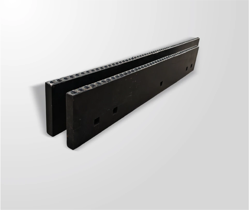
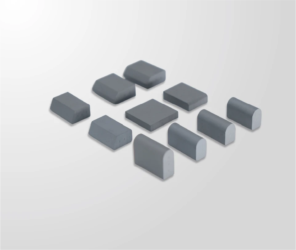
The isolated insert design is one construction choice among several, and it is most valuable where impact-heavy duty makes crack propagation the dominant failure mode. The packed ice carbide kit page describes the isolated layout for ice-breaking duty, and the carbide inserts page covers the component side of the design.
To evaluate the construction for your routes, send the impact profile, the failure history, and the equipment details through the contact page and ask for the configuration and trial terms. The crack-resistant construction is chosen when the route evidence shows that cracks are the problem, and the trial proves the design holds.
Expert view — SENTHAI engineering team: “The crack that cannot travel is the crack that cannot kill the edge. Isolation is the design’s insurance.”
Frequently Asked Questions
What is an isolated insert design? It is a blade construction where each carbide insert is a distinct unit, separated from its neighbors, so a crack in one insert has no continuous path to the next.
Why do cracks spread in continuous designs? A crack follows the material, and a continuous row gives it a path from insert to insert. The boundary between isolated units is where the path stops.
Does isolation reduce cutting performance? No. The isolation is a structural feature; the carbide still does the cutting. The design prevents lateral cracking while maintaining the working edge.
How do I verify the design? Run a sample on an impact-heavy route and inspect whether damage stays contained to the struck insert. Compare the pattern with a continuous-edge blade.
What does the design do for maintenance? A blade with isolated inserts can lose one insert and keep working, giving the fleet a window for planned repair instead of an emergency changeout.
Where is the design most valuable? On impact-heavy duty where crack propagation is the dominant failure mode, such as ice-breaking corridors with repeated high-speed impacts.
Does SENTHAI use this design? SENTHAI describes isolated carbide inserts in its packed ice carbide kit as a crack-prevention feature, with samples available for field verification.
Sources
Related articles
 Best Snow Plow Blade Family for Your Fleet: Top 5 ScenariosKnowledge
 Top 10 Snow Plow Blade Types for Winter Fleets (Ranked by Duty Fit)Knowledge
 Top 5 Best Carbide Blade Configurations for Highway PlowingKnowledgeBest Snow Plow Blade Materials Ranked: Steel vs Carbide vs Cladding vs Rubber-CarbideKnowledge