
Reading Wear Indicators on JOMA-Style Blades: A Maintenance Field Guide
Wear indicators exist to protect your hardware, not just to tell you when to buy a blade. On a JOMA-style segment from SENTHAI's blade line, the indicator is the early warning that the carbide…

Wear indicators exist to protect your hardware, not just to tell you when to buy a blade. On a JOMA-style segment from SENTHAI’s blade line, the indicator is the early warning that the carbide is nearing its service limit, and reading it correctly is what lets the fleet schedule the replacement before the worn edge damages the mounting hardware or fails on the route.
This article is a field guide to reading wear indicators on JOMA-style blades: where to look, the three-step reading routine, how to record wear across the fleet, and what the indicators do not tell you.
Wear indicators exist to protect your hardware
The wear indicator’s job is to separate “time to plan a changeout” from “the blade has failed.” A blade that runs past its wear limit does not stop cutting quietly; it starts damaging the things around it. The exposed steel wears, the mounting hardware takes load it was not designed for, and the plow’s performance drops while the damage compounds.
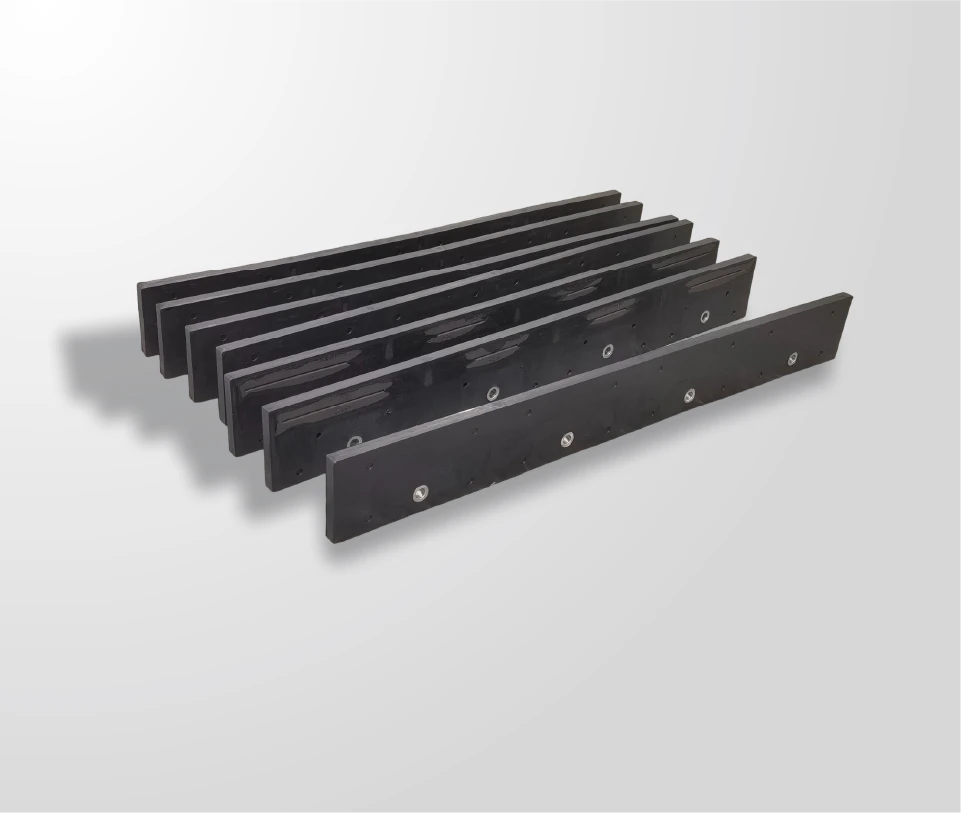
SENTHAI describes its Joma-style sections as including integrated wear indicators that allow operators to monitor the blade’s condition and schedule maintenance before any damage occurs to the plow’s mounting hardware. That sentence is the design intent: the indicator is a maintenance planning tool, not a decoration.
The fleet that reads the indicators on schedule replaces sections in the shop; the fleet that ignores them replaces them on the route. The difference is the cost of a planned changeout versus an emergency one.
Where should you look on each segment?
The indicator is built into the segment, and the inspection has to look at the right place:
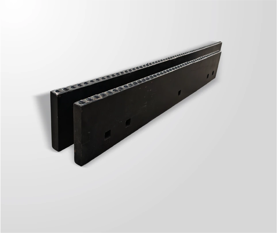
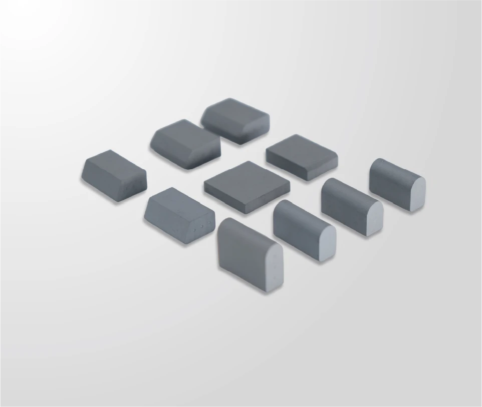
- The working edge, where the carbide meets the pavement and wears first;
- The indicator zone, the designed reference point that shows how much of the carbide is left;
- The transition area, where the carbide and the steel meet, because wear there signals the limit is near;
- The rubber shell around the wear zone, because the rubber protects the structure as the carbide wears.
The exact position of the indicator on a segment is a design detail that the product drawing and the maintenance guide define. The field habit is the same for every position: find the reference, compare the current condition, and record the result.
The inspection position should also be consistent between readers. If one mechanic reads the indicator at the center of the segment and another reads it at the end, the fleet records are not comparable, and the trend becomes noise. The maintenance guide should state exactly where on the segment the reading is taken, and the training should confirm that everyone reads the same point.
The lighting matters too. A wear reference read in poor light is a guess, so the inspection should be done with the segment clean and well lit, which is part of the reason the cleaning step comes first in the routine.
A three-step reading routine
The routine is short enough to run on every segment in the weekly inspection:
Step 1: Clean the zone. Wipe the indicator area and the working edge, because ice, salt, and grime hide the reference.
Step 2: Compare against the reference. Check the carbide height and the indicator mark against the drawing or the segment’s reference point.
Step 3: Classify the condition. Record the segment as serviceable, nearing limit, or at limit, and note the expected replacement window.
| Reading step | Action | Output |
|---|---|---|
| 1. Clean the zone | Wipe the indicator area and the working edge | A visible, unobstructed reference |
| 2. Compare against the reference | Check the carbide height against the drawing or the segment reference | A distance-to-limit reading |
| 3. Classify the condition | Record the segment as serviceable, nearing limit, or at limit | A replacement window per segment |
The classification is the decision input: serviceable segments stay, nearing-limit segments get a replacement window, and at-limit segments get replaced at the next maintenance window. The routine produces a decision, not just a note.
The classification should also feed the route plan. A segment at limit on a heavy route gets a short window, while the same reading on a light route can carry longer, which is the rotation logic applied at the segment level. The indicator reading and the route assignment together set the replacement date, and the maintenance file records both.
The three-step routine also catches the reading errors that hide the problem: a dirty zone, a wrong reference point, or a rushed glance. The routine exists to make the reading reliable, and the reliability is what makes the indicator worth inspecting at all.
The routine’s value also depends on the threshold definitions. The fleet should write down what “nearing limit” and “at limit” mean for each segment type, with the reference measurements, so the classification is consistent between mechanics and across seasons. A threshold written down is a standard; one carried in someone’s head is a memory.
The same thresholds feed the replacement plan and the stock order, which is why the definitions belong in the maintenance guide and the training.
Written down, they protect the fleet every season.
The written standard is the fleet’s memory.
The memory, applied weekly, is the routine that saves the hardware.
The hardware saved is the cost avoided, and the routine is the reason.
Read the indicator, record the reading, and replace on the plan.
How do you record wear across the fleet?
The record is what turns the reading into fleet data:
- Segment location and plow;
- The reading date and the condition class;
- The route group the segment serves;
- The replacement window assigned;
- The actual replacement date and the reason.
The fleet record shows the wear patterns per route group, the intervals per segment type, and the routes where the indicators reach the limit fastest. That data drives the replacement schedule, the stock plan, and the next specification, which is why the record belongs in the maintenance file rather than on a clipboard that gets lost.
The record also supports the supplier conversation. When a route group wears through segments consistently faster than the rest, the fleet can show the supplier the indicator readings and the intervals, and the conversation moves from “the blades are no good” to “these conditions are wearing the carbide at this rate, what configuration changes the outcome.” The data is the difference between a complaint and an investigation.
What if the indicator reaches the limit before the season ends? That is the signal to replace at the next maintenance window and to review the route and the configuration. The indicator did its job; the question is why the wear was faster than planned, and the record answers it.
What indicators do not tell you
The indicator tells you the carbide is nearing its limit; it does not tell you everything:
- It does not reveal the bond condition, so a segment can fail from a weak bond before the indicator is reached;
- It does not reveal impact damage, so a chipped insert or a cracked segment needs its own check;
- It does not predict the route, so the same indicator reading means different remaining life on different surfaces;
- It does not replace the installation check, because a segment installed badly will fail regardless of the indicator.
The wear indicator is one input in the inspection, not the whole inspection. The segment needs the same visual and bond checks as any blade, with the indicator as the wear reference on top.
Build indicator checks into weekly rounds
The value of the indicator is in the routine. Build the reading into the weekly inspection round, with the three-step routine, the record sheet, and the replacement window logic. The JOMA-style blade page is the product reference, and the maintenance guide confirms the indicator position and the segment plan.
To align the routine with the actual product, send the maintenance schedule and the segment inventory through the contact page and ask for the wear reference and the replacement criteria. The indicator protects the hardware; the routine protects the fleet.
Expert view — SENTHAI engineering team: “The indicator is the segment’s honesty. Read it on schedule, and the replacement becomes a plan instead of a surprise.”
Frequently Asked Questions
What is the purpose of a wear indicator? It marks the point where the carbide is nearing its service limit, so the fleet can schedule the replacement before the worn edge damages the mounting hardware.
Where is the indicator on a JOMA segment? The indicator is built into the segment at a designed reference point near the working edge. The product drawing and the maintenance guide define the exact position.
How often should I read the indicators? In the weekly inspection round, with the three-step routine: clean, compare, classify. The reading takes seconds per segment.
What should the record include? Segment location, reading date, condition class, route group, replacement window, and the actual replacement date and reason.
What do indicators not reveal? Bond condition, impact damage, and the route’s effect on remaining life. The indicator is one input, not the whole inspection.
How do I decide the replacement window? Use the condition class and the route group: nearing-limit segments on heavy routes get a short window, and those on light routes can carry longer.
Does SENTHAI confirm the indicator reference? SENTHAI describes integrated wear indicators on its Joma-style sections; the maintenance guide and the engineering team confirm the reference and the criteria.
Sources
Related articles
 Best Snow Plow Blade Family for Your Fleet: Top 5 ScenariosKnowledge
 Top 10 Snow Plow Blade Types for Winter Fleets (Ranked by Duty Fit)Knowledge
 Top 5 Best Carbide Blade Configurations for Highway PlowingKnowledge
 Best Snow Plow Blade Materials Ranked: Steel vs Carbide vs Cladding vs Rubber-CarbideKnowledge