
Insert Layout and Blade Life: How Carbide Placement Changes Wear
Layout is blade design. The way carbide inserts are placed, spaced, angled, and isolated decides how the blade wears, how it survives impacts, and how long it lasts. Two blades with the same carbide…
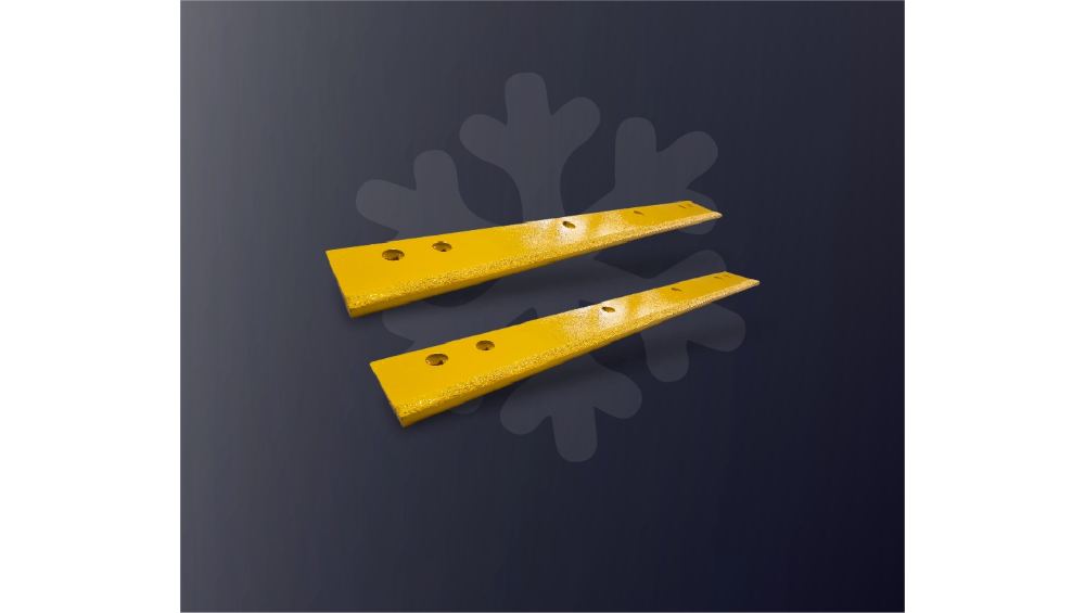
Layout is blade design. The way carbide inserts are placed, spaced, angled, and isolated decides how the blade wears, how it survives impacts, and how long it lasts. Two blades with the same carbide can behave completely differently because the layout differs, which is why the layout belongs in the specification rather than in the factory’s default.
This article explains how insert layout affects blade life: spacing, angle, and isolation, the crack-fighting logic, the differences across blade types, and how to specify the layout in custom work.
Layout is blade design
The insert layout is the blade’s design decision: where the carbide meets the road, how much steel is exposed, and how the impacts spread across the edge. The layout answers the questions that the material alone cannot:
- Where does the edge cut hardest?
- How much steel is exposed to the surface?
- How do the impacts travel across the edge?
- How does the wear develop over the season?
The layout is the interface between the material and the application, and it is the part of the design that the route data should drive. A layout specified for an abrasive highway is not automatically right for an impact-heavy residential route.
The layout is also the part of the design that is easiest to change incorrectly. Swapping the insert shape without reviewing the spacing and the angle changes the layout’s behavior, and the blade that was ordered as a system becomes a collection of parts. The layout review belongs with every insert change, standard or custom.
The same review should be documented: the layout as ordered, the route it was ordered for, and the wear and failure data that came back. The layout record is the design history, and the history is what the next specification starts from.
How do I know if the layout is wrong for my route? The wear pattern and the failure mode tell you: rapid edge loss points to the spacing or the angle, and chipping or insert loss points to the isolation and the toughness. The record of the pattern is the diagnosis.
How do spacing, angle, and isolation affect wear?
The layout parameters each change the wear story:
| Layout parameter | How it affects wear |
|---|---|
| Spacing | Tight spacing gives continuous cutting but concentrates wear at the tooth edges; wider spacing is cheaper but exposes more steel |
| Angle | A steeper attack angle cuts harder and loads the leading edge more |
| Isolation | Separated inserts contain impact damage so a cracked insert does not take the row with it |
| Position | The layout across the edge decides where the wear concentrates |
Each parameter is a lever, and the levers work together. The layout that balances cutting, wear, and impact is the layout that lasts.
The levers also interact with the carrier and the bond. A spacing that exposes too much steel, an angle that concentrates the load, and an isolation that leaves the inserts under-supported can each turn a good carbide grade into a premature failure. The layout review has to cover the whole system, not the inserts alone.
The same system view applies to the manufacturing: the layout is machined into the carrier, the inserts are seated and brazed, and the process control decides whether the layout on the drawing is the layout on the blade. The drawing and the batch records are the layout’s evidence.
What is the first layout question to ask? What failure is the layout solving: wear, chipping, or insert loss. The layout follows the failure, and the failure history is the first input.
How layout fights cracking
Cracking is a layout problem as much as a material problem:
- A continuous row gives a crack a path from insert to insert;
- An isolated layout breaks the path, containing the damage;
- The spacing and the steel between the inserts decide how the load transfers;
- The angle and the geometry decide where the stress concentrates.
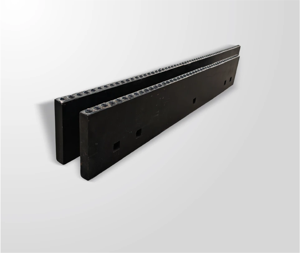
SENTHAI describes the isolated insert design in its packed ice kit as preventing lateral cracking, and the principle applies across blade types. The layout that fights cracking is the layout that keeps the edge working after an impact.
How does layout differ across blade types?
The layout follows the duty:
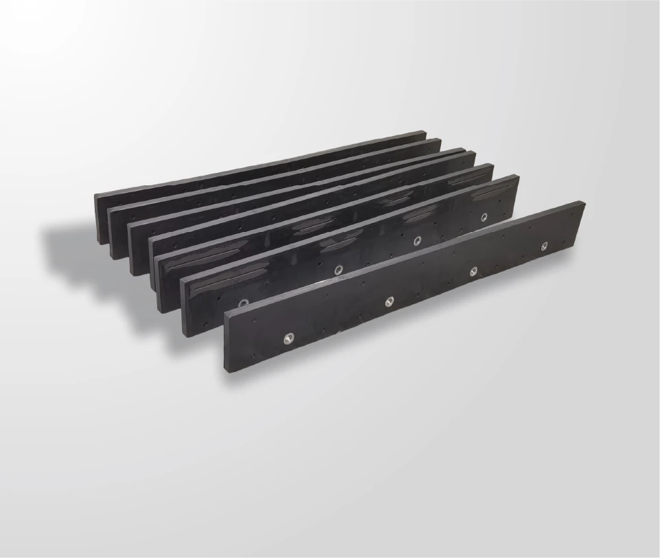
- Carbide snow plow blades: brazed inserts in a line along the edge, spaced for the abrasive duty, with the layout matched to the contact band;
- JOMA-style segments: inserts brazed into the steel segments, with the segment layout and the rubber encasement adding the flex and the isolation;
- Packed ice kits: dome-head inserts in an isolated layout, engineered for the fracture duty and the crack containment;
- Bucket and wear edges: insert spacing matched to the material and the impact profile.
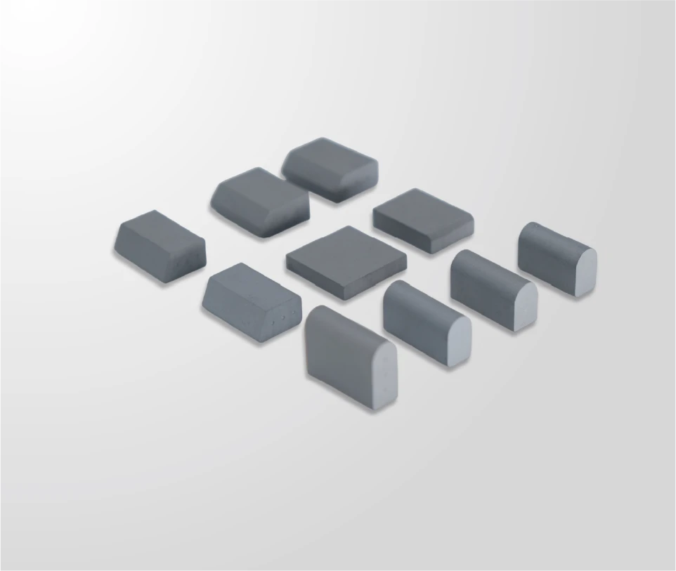
SENTHAI’s carbide inserts page covers the insert side, and the packed ice carbide kit page shows the isolated layout in practice. The layout is the design layer that ties the inserts to the blade, and the carbide snow plow blade page shows how the same layout logic carries into the full blade construction.
The layout comparison between blade types is also the maintenance comparison: the line layout wears as a continuous band, the segmented layout wears per segment and per insert, and the isolated layout fails per insert with the containment. The inspection routine follows the layout, and the record shows which layout the route rewards.
The same comparison feeds the fleet’s blade mix: the route that punishes a continuous line, or rewards the isolation, is the route that decides which blade family belongs there. The layout is the technical reason behind the route assignment.
The assignment, documented with the layout and the route data, is the fleet’s blade plan, and the plan is reviewed with the manufacturer at the specification stage. The layout is the design layer that connects the route to the order.
The connection, kept current with the wear data, is the layout’s long-term test, and the test is what the next design iteration starts from.
The iteration, guided by the data, is the blade’s improvement over its seasons, and the improvement is the layout’s payoff.
The payoff, measured in the changeout log, is the design’s verdict, and the verdict is the layout’s long-term report.
The report, reviewed with the manufacturer, is the next layout’s starting point.
How does the layout affect the inspection? The layout decides what the inspection looks for: the continuous band for the line layout, the segment and the bond for the segmented layout, and the individual insert and the containment for the isolated layout.
Specifying layout in custom work
The custom layout is a drawing decision:
- Name the insert shape, the size, and the grade;
- Specify the spacing and the position across the edge;
- State the angle and the geometry;
- Confirm the isolation where the crack risk is high;
- Define the acceptance criteria for the layout.
The custom drawing should be reviewed with the manufacturer, because the layout interacts with the steel carrier, the bonding, and the manufacturing process. The drawing is the contract, and the review is where the layout becomes manufacturable.
Design the edge around your route
The layout should be designed around the route: the abrasive corridors get the spacing and the angle for the wear, the impact corridors get the isolation and the toughness, and the mixed routes get the balance. The insert layout reference is the insert reference, and the contact page is where the layout and the configuration are confirmed.
Send the route profile, the failure history, and the equipment details through the contact page and ask for the layout recommendation. The layout is the design, and the design is the blade life.
Expert view — SENTHAI engineering team: “The layout is the design, and the drawing is its contract. Spacing, angle, and isolation are the blade’s plan.”
Frequently Asked Questions
Why does insert layout matter? The layout decides where the edge cuts, how much steel is exposed, how the impacts spread, and how the wear develops. It is the blade’s design decision.
What does spacing change? Tight spacing gives continuous cutting and less exposed steel; wider spacing is cheaper but wears the steel between the teeth.
What does the angle do? The attack angle sets the cutting aggression and the load concentration. A steeper angle cuts harder and wears the leading face faster.
How does layout fight cracking? Isolation breaks the crack path, containing the damage to one insert instead of taking the row. The spacing and the steel between the inserts also transfer the load.
How does the layout differ across blade types? Each duty has its layout: the line for carbide blades, the segments and the rubber for JOMA, the isolated domes for the ice kits, and the spacing for the bucket edges.
How do I specify a custom layout? Name the shape, size, grade, spacing, position, angle, isolation, and acceptance criteria on the drawing, and review it with the manufacturer.
What should I send for a layout recommendation? The route profile, the failure history, and the equipment details. The layout follows the duty.
Sources
Related articles
 Best Snow Plow Blade Family for Your Fleet: Top 5 ScenariosKnowledge
 Top 10 Snow Plow Blade Types for Winter Fleets (Ranked by Duty Fit)KnowledgeTop 5 Best Carbide Blade Configurations for Highway PlowingKnowledge
 Best Snow Plow Blade Materials Ranked: Steel vs Carbide vs Cladding vs Rubber-CarbideKnowledge