
What Are the Exact JOMA Blade Torque Specs for Mounting Hardware?
Maintaining the structural integrity of a segmented snow plow system relies entirely on the security of its clamping mechanism. Under-torqued mounting hardware inevitably leads to severe vibration, joint fretting, and bolt fatigue, while over-torquing…
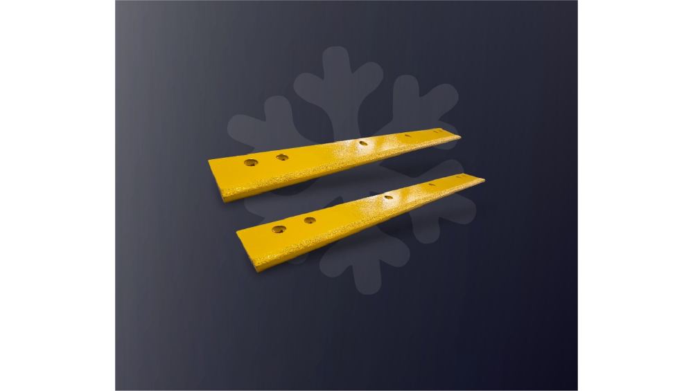
Maintaining the structural integrity of a segmented snow plow system relies entirely on the security of its clamping mechanism. Under-torqued mounting hardware inevitably leads to severe vibration, joint fretting, and bolt fatigue, while over-torquing can stretch threads, distort clamping bars, and cause premature fastener failure. This technical guide outlines the precise torque guidelines, proper seating patterns, and critical retorque protocols required to secure JOMA-style plow blades for high-vibration winter operations.
Understanding JOMA-Style Blade Fastener Engineering
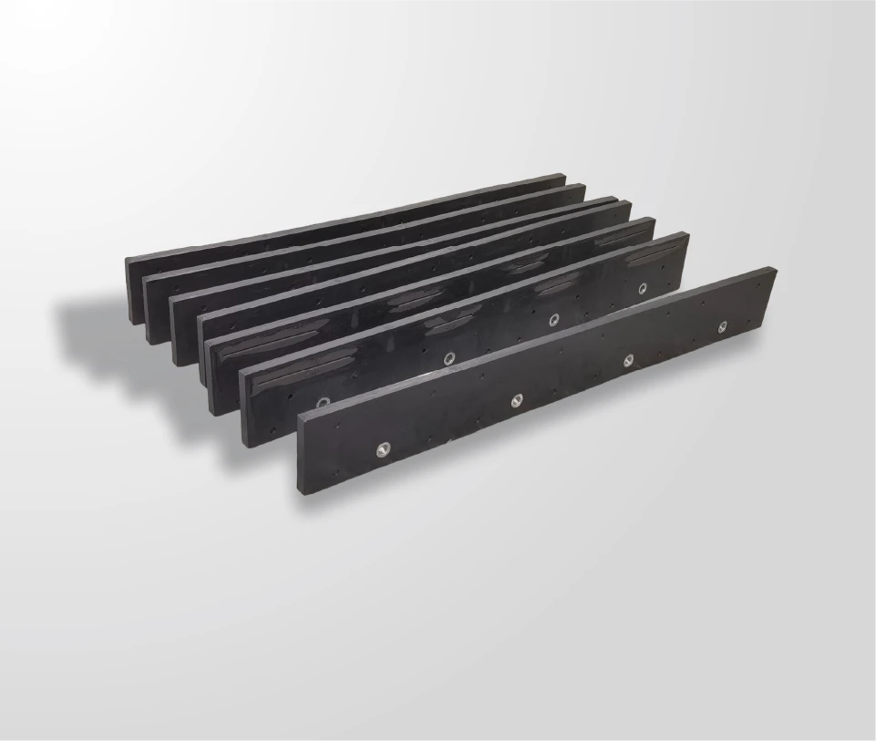
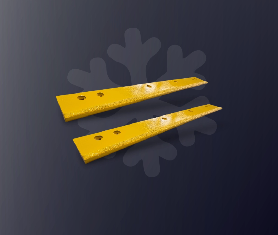
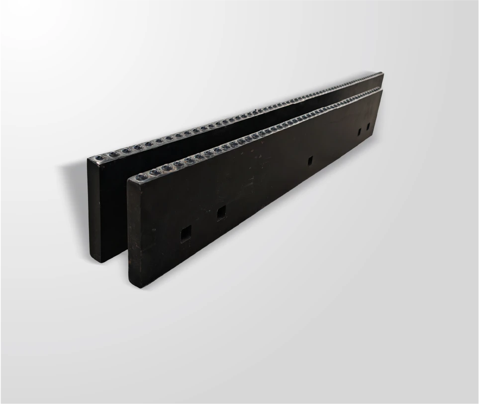
The standard JOMA-style segmented plow blade architecture is engineered around specific 12-inch mounting intervals, a specialized heat-treated clamping bar, and high-tensile Grade 8 (or better) carriage bolts. Because these multi-segment systems must flex slightly to absorb road contours while remaining rigidly bound to the moldboard, achieving the correct fastener clamp load is vital.
A common industry misconception is that physical fitment equates to proper clamping pressure. For example, a standard 5/8-inch bolt will easily slip through the mounting holes of various assemblies, but the required torque can vary drastically based on thread pitch, nut lubrication, washer type, and overall moldboard thickness. To ensure structural safety, operators must always prioritize original equipment manufacturer (OEM) specifications over general reference charts. Where official documentation is unavailable, standard heavy-duty engineering guidelines govern the installation.
Recommended Torque Ranges for Heavy-Duty Plow Fasteners
When OEM documentation does not provide a specific proprietary figure, technical manuals generally point to standard industry engineering guidelines. For example, many standard installation frameworks direct operators to follow the SAE J1701 standard for general torque recommendations.
The following data serves as a verified practical field reference for unlubricated, clean Grade 8 fasteners commonly utilized in heavy-duty JOMA-style mounting setups:
| Bolt Diameter | Fastener Grade | Recommended Reference Torque |
| 1/2 in. | Grade 8 or Better | 90 ft-lb |
| 5/8 in. | Grade 8 or Better | 175 ft-lb |
| 3/4 in. | Grade 8 or Better | 319 ft-lb |
In standard commercial fleet operations, 5/8-inch and 3/4-inch Grade 8 carriage bolts form the backbone of the blade assembly. While certain heavy-duty component manuals explicitly list a specification of 220 foot-pounds for specific proprietary JOMA-style carriage bolt kits, this figure must be treated as application-specific. Forcing a blanket 220 ft-lb specification onto a standard 5/8-inch bolt without verifying thread variables can over-stretch the metal, causing catastrophic shear failure mid-route.
The Critical Role of Non-Reusable Hardware and Washers
Executing a successful segment swap requires replacing the entire mounting hardware set. Reusing old bolts, even those that appear clean and undamaged to the naked eye, introduces severe operational risks:
-
Microscopic Thread Stretch: Bolts tightened to high clamping thresholds experience permanent elongation, altering the thread pitch and drastically reducing future holding power.
-
Loss of Nut-Locking Efficiency: Prevailing torque locknuts or nylon-insert nuts lose their friction-locking capability after a single removal cycle, making them highly susceptible to backing off under highway vibrations.
-
Mating Surface Fatigue: Deformed bolt heads and scored shoulders prevent uniform seating against the clamping bar.
Furthermore, the utilization of hardened flat washers is a non-negotiable engineering requirement. High-tensile hardened washers distribute the immense clamping forces evenly across the slot, protecting the softer steel of the moldboard from localized indentation. If a soft, non-hardened washer is substituted, it will cup and deform under stress. This deformation causes the joint to relax shortly after installation, rendering the original torque wrench reading completely irrelevant.
The Three-Pass Seating and Tightening Pattern
An unevenly seated blade creates internal structural stress that guarantees localized loosening and premature segment wear. A plow blade assembly must never be torqued in a single, continuous pull from one end to the other. Instead, technicians must utilize a disciplined, center-out three-pass cross pattern to ensure the full cutting-edge system settles uniformly against the moldboard face.
-
Step 1: Preparation and Inspection: Completely clean all mating surfaces on the moldboard and clamping bar. Use a wire brush to remove rust, packed salt, scale, and paint buildup that could compress and loosen later. Ensure there is a minimum 2-inch backing support below the mounting holes and a 2.5-inch clearance above them. If the moldboard face is severely worn or uneven, install an engineered adapter blade or backing blade to establish a flat foundation.
-
Step 2: Pre-Seating Pass: Align the segments and install the fresh Grade 8 hardware kit. Using a standard hand wrench or a calibrated impact tool set to low power, tighten all fasteners to roughly 50 percent of the final target torque value. Always start with the fasteners in the dead center of the blade and alternate outward toward the left and right wings.
-
Step 3: Final Torque Pass: Using a calibrated click-type or digital torque wrench, return to the center fasteners and bring every nut up to full torque specification (e.g., 175 ft-lb for standard 5/8-inch Grade 8 setups) utilizing the exact same center-out alternating sequence.
-
Step 4: Final Verification Pass: Perform a final continuous check from one end of the blade to the other, verifying that no fasteners skipped or experienced joint relaxation during the secondary tightening pass.
The Early-Service Retorque Protocol
The most critical phase of securing a heavy-duty plow blade occurs after it leaves the shop and enters active service. As the vehicle encounters sub-zero temperatures, pavement shocks, and high-frequency vibrations, the microscopic ridges on the freshly clamped steel surfaces begin to settle and smooth out. This mechanical settling naturally causes joint relaxation.
To counteract this, fleets must enforce a strict early-service retorque protocol:
-
Initial Operational Check: Stop the vehicle and re-torque the full fastener set after the first 4 to 10 hours of active plowing.
-
Inspection Protocol: Apply the torque wrench to each nut at its full target setting. If a fastener turns significantly before the wrench clicks, it indicates the joint has relaxed. If multiple fasteners across a single segment show significant loss of tension, the hardware stack must be completely disassembled, inspected for pocket misalignment or thread damage, and replaced.
-
Fleet Documentation: For standard operating procedures (SOPs), record the specific torque wrench used, the technician responsible, and the exact hardware condition to ensure full compliance and liability safety.
Sourcing Engineered Components for Fleet Standardization
When standardizing replacement workflows across a municipal or commercial fleet, procurement managers must look beyond the cutting edge itself and evaluate the entire hardware ecosystem. Opting for professional hardware configurations, such as SENTHAI snow plow blades and JOMA-style replacement components, ensures that every piece of the assembly is engineered to withstand identical levels of clamp stress and structural vibration.
Utilizing complete, pre-matched hardware kits—containing verified Grade 8 carriage bolts, hardened washers, and high-strength locknuts—eliminates maintenance guesswork in the bay. It ensures that field teams always have access to identical fastener classes, streamlining the installation path across diverse truck fleets and safeguarding the system against the common failures associated with mismatched, mixed-grade components.
Related articles
 Best Snow Plow Blade Family for Your Fleet: Top 5 ScenariosKnowledge
 Top 10 Snow Plow Blade Types for Winter Fleets (Ranked by Duty Fit)KnowledgeTop 5 Best Carbide Blade Configurations for Highway PlowingKnowledge
 Best Snow Plow Blade Materials Ranked: Steel vs Carbide vs Cladding vs Rubber-CarbideKnowledge