
Welding Versus Brazing Carbide: Heat Input and Cracking Risk
The question of welding vs brazing carbide usually arrives after a failed repair rather than during design. A tip that was "welded back on" in the workshop cracks within a shift, and the conclusion…
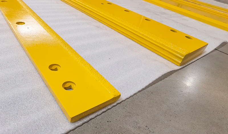
The question of welding vs brazing carbide usually arrives after a failed repair rather than during design. A tip that was “welded back on” in the workshop cracks within a shift, and the conclusion drawn is that the part was bad. The real difference is heat: brazing joins the two materials below the point where either melts, while welding melts steel and, in doing so, puts a cemented carbide through a temperature cycle it was never designed to survive.
What Each Process Actually Does
Brazing bonds; welding fuses the steel.
Brazing fills a joint with a molten filler that wets both surfaces and solidifies below the melting point of either, while welding melts the steel itself and creates a cast structure at the joint.
The distinction is thermal, not semantic. Brazing fillers melt in a range that sits well below the melting point of steel, commonly in the region of 600 to 900 degrees Celsius depending on the alloy, and the process relies on capillary action to draw the filler into a close-fitting gap. The base materials stay solid. Welding does the opposite: an arc, a gas flame or a resistance process melts the steel locally, reaching temperatures far above the melting point of steel, and the molten pool solidifies into a joint that is metallurgically part of the parent metal.
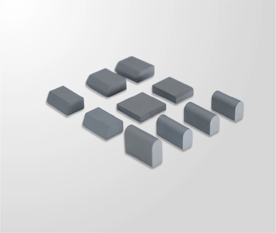
Cemented carbide tolerates the first and not the second. The cobalt binder in a carbide grade softens and degrades well below steel welding temperatures, and the thermal shock of a molten pool next to a brittle insert produces cracks that may appear immediately or after the part cools. That is why carbide inserts are brazed, mechanically retained, or set into a steel body, and why the repair that looks like welding is usually welding of the steel carrier with the carbide handled separately.
The practical terminology matters when specifying work. Hardfacing, in which carbide particles are carried in a weld-deposited matrix, is a different family of process again, and is described in the material literature published by organisations such as AMPP and in welding society resources from the American Welding Society.
Heat Input and Residual Stress
Heat input decides what happens to the joint after it cools. In any dissimilar-material joint, the two materials expand and contract at different rates, and the filler and the surrounding steel add their own contributions. The result is residual stress concentrated along the interface.
Brazing controls that stress through a lower working temperature and a distributed heat source. An induction process heats the assembly in a controlled ramp, holds briefly while the filler flows, and cools under control so that the joint is not quenched. Because the carbide never approaches its degradation range, the material either side of the bond retains the structure it was supplied with.
Welding loads the same interface with a much larger thermal cycle. The steel beside the joint is heated to melting and then cools rapidly into the surrounding mass, which is the classic condition for a hard, crack-prone heat-affected zone. Where welding is used on an assembly, the carbide is normally positioned so that the weld heat does not reach it, and the sequence is planned around that constraint.
Heat input also affects the finish and fit of the part. Distortion from a weld can move a machined pocket or a bolt line, and the pockets on a carbide wear part are held to close dimensional tolerance for exactly this reason. The process fundamentals of brazing, including why the filler temperature sits below the base material melting range, are described by the TWI brazing explainer.
Cracking Mechanisms and Their Triggers
Cracking in and around a joined carbide part has three distinct triggers, and identifying which one applies is what makes a repair last.
The first is thermal. A rapid heat cycle, whether from an arc or from a torch applied too locally, creates a steep temperature gradient. The surface expands against the cold mass behind it, and because cemented carbide has limited capacity to deform, a crack initiates at the insert or along the joint line. The trigger is the rate of change rather than the peak temperature alone, which is why a slow controlled ramp is more important than a lower setting.
The second is mechanical. A joint that is only partially bonded concentrates load on the bonded area, and a joint with a void at one end of an insert loads the opposite end in tension. The failure then appears as a shed insert under normal service load, with no visible abuse of the machine. This is a process trigger, addressed by surface preparation, filler selection and the cycle rather than by using a tougher grade.
The third is geometric. An insert with little material behind the working edge, or one that stands proud of the body, sees a stress concentration at exactly the point where the load arrives. Geometry and grade are design variables, and a part that has failed at the tip for the third time usually needs a change in the insert profile or the pocket depth rather than a different joining process.
Where Each Process Is Repairable
Steel joints can be repaired in the field.
A welded steel structure can be cut back and re-welded in a workshop or on site, while a brazed carbide joint is a controlled production operation and is not normally a field repair.
That difference has real consequences for a fleet. Steel components — moldboards, carriers, brackets, blade bodies — can be welded anywhere with the right equipment, and a contractor can keep a machine working with a repair rather than ordering a part. A brazed carbide insert, by contrast, needs a controlled heat source, correct surface preparation, the right filler and a defined cooling profile to be replaced properly. Attempting it in a field workshop is how a good blade body ends up scrapped.
The practical field decision is therefore about the steel, not the carbide. Where a body is sound and only the inserts are worn or lost, the part goes back to a proper brazing operation or is replaced; where the body itself is damaged, it can be repaired as steel and returned to service. Mechanical retention changes the calculus again, because a retained insert can be replaced with hand tools — the trade-off between bonded and mechanically retained inserts, and when each is appropriate, is set out in the article on insert retention.
Fitment and Design Consequences
The joining process sets constraints on the design of the part, and those constraints show up as fitment requirements.
A brazed insert needs a pocket that holds the filler and provides enough bond area for the load, and the pocket dimensions are machined to close tolerance so the insert seats consistently. The grade also has to be qualified for the cycle, which narrows the range of carbide a designer can choose from. In exchange, the part is rigid with no fasteners to loosen, and the insert can be positioned exactly where it is needed on the wear profile.
A welded assembly has more freedom in the steel but must keep heat away from any carbide, which generally means the carbide is a separate item. Mechanically retained inserts need pockets with a retention feature, and the interface has to tolerate movement without loosening. Each route constrains the bolt pattern or the pocket footprint, and the equipment interfaces that these parts mount to follow conventions published by SAE.
Fitment is also where a distributor or OEM feels the process decision most directly. A brazed assembly is ordered once to a drawing because it cannot be adapted on site; a retained insert system is ordered as a kit and assembled by the customer.
Cost and Equipment Requirements
The cost comparison between welding and brazing is mostly about equipment and repeatability rather than unit cost.
Welding is the more accessible process: a power supply, consumables and a competent operator are available almost everywhere, and the equipment is already in most maintenance shops. The cost is borne later, in heat-affected zones, in distortion and in parts that cannot be used with carbide.
Brazing for production needs more than a torch. Matching the filler to the joint, controlling the heating cycle, capturing the process data and verifying the result on a sectioned sample all require tooling and discipline, which is why it is normally a production operation rather than a repair one. Where it is done at scale, induction heating is the usual method because the heat is generated in the work piece and the cycle can be repeated exactly; the controlled line at SENTHAI, described on the factory page, uses automated high-temperature induction brazing and welding with annealing as part of a chain that also covers pressing, sintering, finishing and vulcanization.
Equipment on the workshop side carries its own obligations. Hot work, fume control and guarding are covered by general industry regulation such as 29 CFR 1910, and the joining of a specific assembly should be described in a procedure rather than left to the operator. Filler metal data for the alloys involved is published by suppliers such as Lucas Milhaupt, and material references such as those from ASM International describe how the joint area behaves under load.

Choosing by Component Size and Duty
The choice between the two families in practice is driven by component size, load path and how the part is expected to be maintained.
| Point | Welding | Brazing |
|---|---|---|
| What melts | Steel, locally, plus filler | Filler only |
| Effect on carbide | Not compatible with a carbide insert in the joint | Designed for it, within a controlled cycle |
| Joint character | Fused, part of the parent steel | Bonded across the full interface and fillet |
| Heat-affected zone | Present in the steel; needs control | Limited by cycle design |
| Repairability | Possible in a workshop or in the field | Production operation, not a field repair |
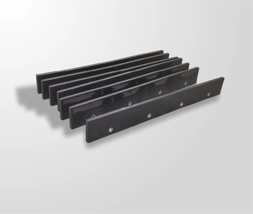
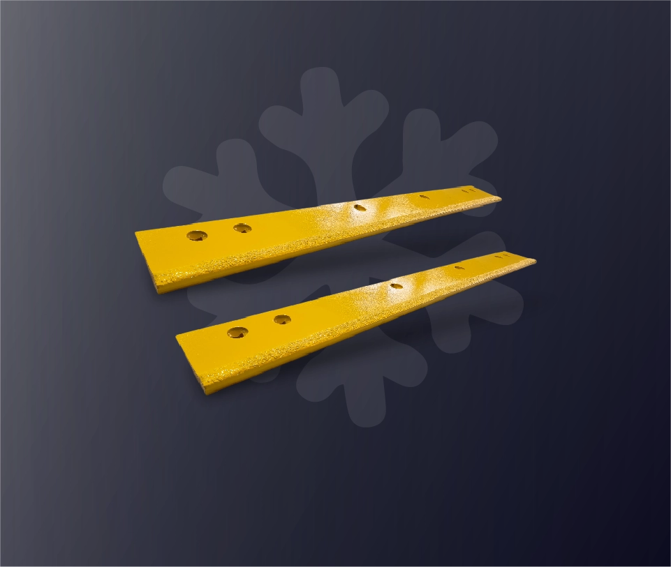
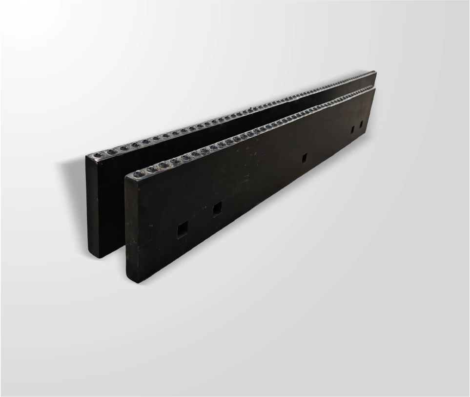
| Typical fit | Steel structures, carriers, brackets, hardfaced surfaces | Carbide-edge assemblies on mouldboards and plows |
Three practical rules follow. Keep the carbide out of the weld: join steel to steel by welding and carbide to steel by brazing or retention. Match the process to the access available for maintenance, because a joint that cannot be serviced where the machine runs will eventually be improvised there. And specify the process on the drawing, together with the grade it is qualified for, so that a repair yard does not make the decision on the spot with the equipment it happens to have.
Brazing and welding are separated by temperature, and that single difference decides what can be joined to what. Brazing keeps both parent materials solid and is therefore the process that lets a carbide insert be attached to a steel body without degrading it; welding melts steel and is the right answer for the structure and the carrier, but not for a joint that includes carbide. Heat input, residual stress and cracking all follow from that, as does repairability: steel can be repaired almost anywhere, while a brazed insert belongs to a controlled production cycle. The specification should name the process, the grade it suits and the verification that proves the joint.
Send SENTHAI the assembly drawing, the carbide grade and the duty the part works in, and the technical team will review the joining process, the joint geometry and the fitment tolerances for the application.
Frequently Asked Questions
Can you weld carbide directly to steel?
Not as a fusion weld that makes the carbide part of the joint. Welding melts steel at temperatures far above the range the cobalt binder in a cemented carbide can tolerate, so the insert cracks or loses its structure. What is done in practice is to weld the steel components of an assembly and attach the carbide by brazing, by mechanical retention in a machined pocket, or by setting it into a steel body that is welded separately. Repair work on a carbide-tipped part should keep the insert out of the weld.
Is brazing weaker than welding?
They are not comparable in that way, because they carry load differently. A fused weld makes the joint part of the parent steel, while a braze bonds across the full interface and fillet, distributing load over the whole pocket area. For a carbide insert, a properly brazed joint is the appropriate design, and a weld that degrades the insert is not a stronger alternative. What limits a brazed joint is process control: incomplete wetting or overheating can reduce its capacity well below design intent.
Why does a carbide tip crack after a field repair?
Almost always because of heat. A torch or an arc applied too locally creates a steep temperature gradient, and carbide has limited capacity to accommodate the resulting stress, so a crack starts at the tip or along the joint line. Rapid cooling adds to it. The other possibility is that the repair left part of the interface unbonded, which concentrates service load on the bonded area and sheds the insert under normal working conditions rather than under abuse.
What should a drawing state about the joining process?
The process, the filler or retention method, the carbide grade qualified for it, and the acceptance criteria for the joint. Stating these on the drawing is what prevents a repair yard from choosing a method based on the equipment it happens to have on the day. Any sampling, test report or documentation agreed for the programme is a commercial matter and is stated in the written quotation or order documents.
Related articles
 How Sintered Carbide Wear Parts Are Made: Powder to Finished PartCarbide grades, metallurgy and joining technology
 Tungsten Carbide Wear Protection: Tile, Rod and Composite OptionsCarbide grades, metallurgy and joining technology
 Inspecting a Braze Joint: Shear, Dye Penetrant and Visual CriteriaCarbide grades, metallurgy and joining technology
 Carbide Hardness and Strength: HRA, HV and Transverse RuptureCarbide grades, metallurgy and joining technology