
Tungsten Carbide Wear Protection: Tile, Rod and Composite Options
Wear protection is usually bought after the first body has been scrapped. A moldboard, a bucket lip, a chute or a hopper wall wears through in a place nobody specified, and the question that…

Wear protection is usually bought after the first body has been scrapped. A moldboard, a bucket lip, a chute or a hopper wall wears through in a place nobody specified, and the question that follows is which form of tungsten carbide wear protection belongs there. Tile, rod and composite overlay are three different answers to that question, and choosing between them is a matter of coverage area, fixing method and the geometry of the wear zone rather than of which material is hardest.
What Each Form Is Designed For
Tile covers area, rod rebuilds edges.
Carbide tile protects large flat or curved surfaces from sliding abrasion, carbide rod builds or restores a hard edge, and composite overlay deposits a wear-resistant layer where a coating is more practical than a plate.
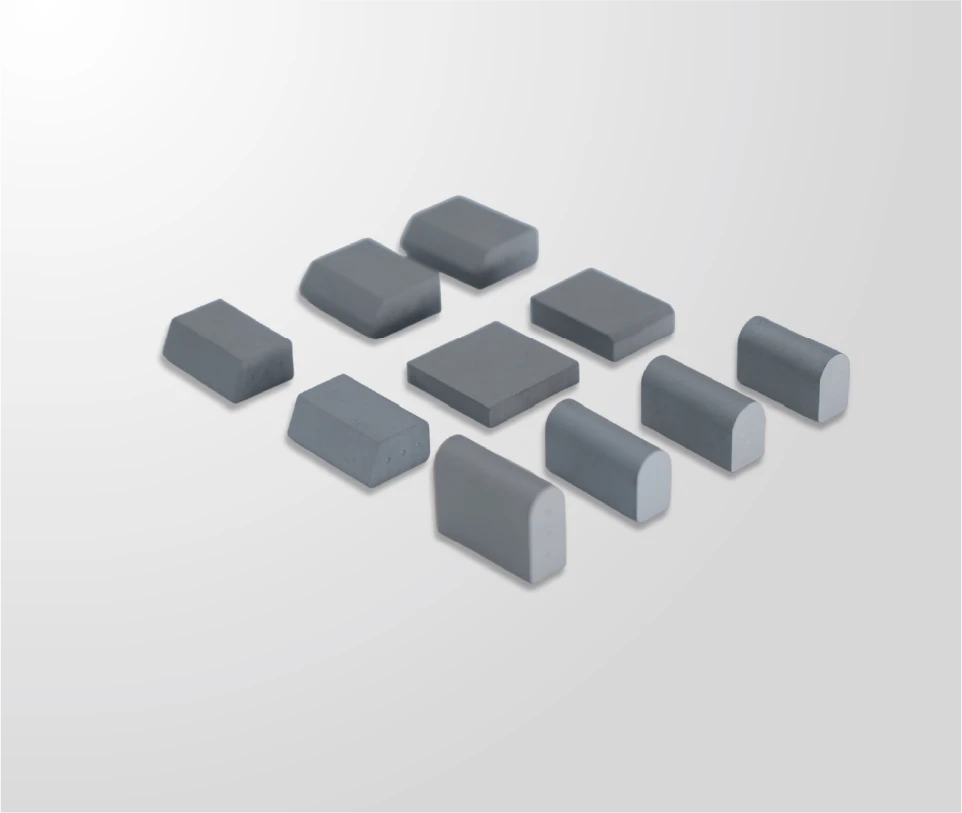
Tile is a set of small cemented carbide pieces — square, rectangular or shaped — bonded to a steel backing or directly to the component, usually in a pattern with gaps that allow the steel between them to take impacts. It is a coverage solution: it protects an area where abrasive material slides, and it is selected when the wear zone is broad rather than at an edge.
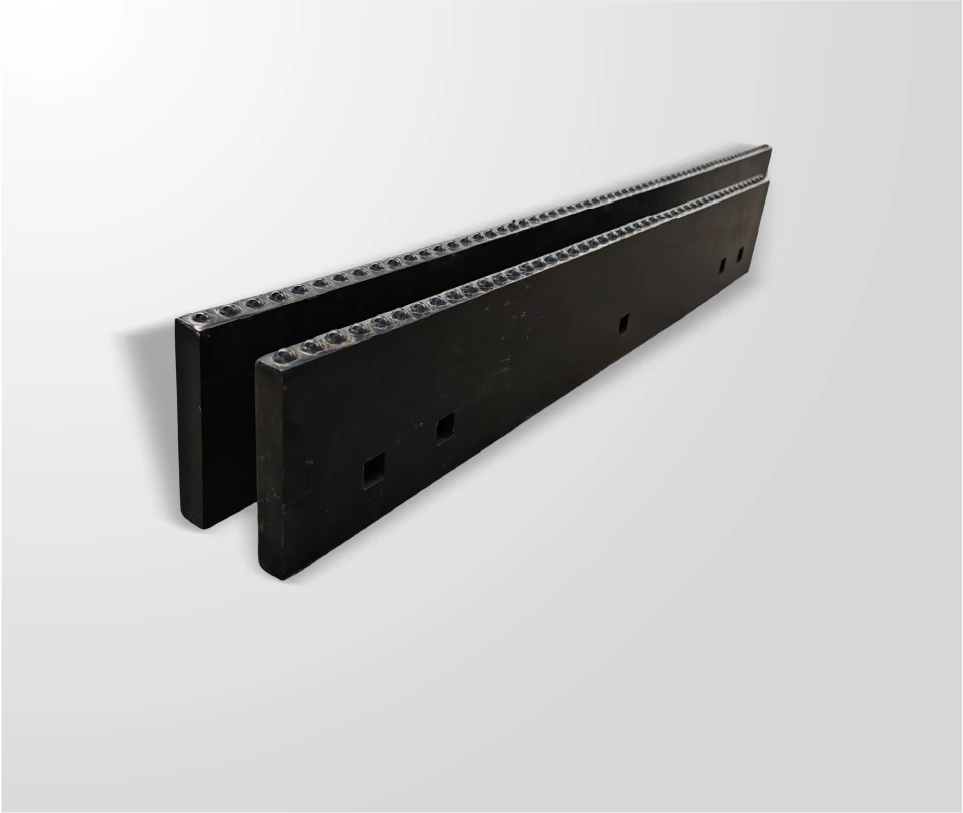
Carbide rod is used where a working edge has to be built up or restored. It is applied by brazing or by a welding process that deposits a carbide-bearing layer, producing a hard, narrow band along an edge rather than a covering over a face. It suits components whose problem is an edge that rounds and loses its cutting function.
Composite and overlay options cover the middle ground: a wear-resistant layer applied over a larger area than a rod would cover but thinner than a tile, used where weight, geometry or access makes tile impractical. Thermal spray coatings with carbide in the matrix are one example, and the families are described by wear protection producers and coating suppliers such as Kennametal and the wear and corrosion practice published by AMPP.
Coverage, Thickness and Wear Allowance
Coverage and thickness are the two numbers that determine how long a protection system lasts, and they are often specified independently when they should be specified together.
Coverage describes how much of the wearing area is protected. A tile pattern covers a proportion of the surface, leaving steel exposed between pieces; the exposed steel wears slightly faster and the tile shields the area behind it. That is deliberate: a solid covering with no gaps transmits every impact directly into the bond line, while a patterned arrangement lets the substrate absorb shock. The proportion and the gap width therefore belong in the specification.
Thickness sets the wear allowance — how much material can be lost before the protection stops protecting. It is consumed at a rate set by the material being handled: angular, silica-bearing aggregate removes material far faster than rounded sand or soft limestone. Where a rod or overlay is used, the equivalent quantity is the deposit thickness and the number of passes, which also determine how much the underlying steel is heated.
The comparison only becomes meaningful when both figures are set against the expected service interval. A thin covering over a wide area may outlast a thick covering in the wrong place, because the wear zone is a region rather than a surface.
How Each Is Fixed to the Machine
By bonding, welding or mechanical fastening.
Tile is bonded with adhesive or brazed, rod and overlay are welded or sprayed, and larger protection plates are bolted so they can be replaced on site.
Bonded tile depends on surface preparation and adhesive performance more than on the carbide. The substrate has to be clean, flat enough for full contact and free of scale, because a bond that is partial concentrates load and lets the tile lift at a corner. Where a tile is brazed instead, the joint behaves like any other brazed carbide joint: the heating cycle and the filler decide the result.
Rod and overlay are applied by a thermal process, so the steel is heated and a heat-affected zone forms underneath. That is acceptable on a thick wear plate and problematic on a thin or highly loaded part, where the heated zone becomes the weakest link. Post-heating and controlled cooling are often needed to avoid cracking, and the resulting hardness profile through the deposit matters as much as the surface figure.
Mechanical fixing through bolts or welded studs is the most serviceable option and the most demanding on design, because every fastener is a hole through the protected material and a potential start point for cracking. The interface conventions for the equipment these parts mount to are published by bodies such as SAE, and each fixing method imposes its own tolerance on the component — a point that matters where pockets and fastening features are machined to close limits.
Where Each Form Fails
At the edge of the covered zone, not in the middle.
Protection systems rarely fail at the centre of the protected area; they fail at the boundary where wear moves into unprotected steel and undermines the covering.
Tile fails in three characteristic ways. A corner lifts when the bond line is incomplete or the substrate flexes. A tile shears when an impact arrives at the unsupported edge of a piece. And the exposed steel between tiles erodes faster than expected, so the pattern becomes unsupported and the tiles start to move. Each of these is addressed by pattern design and surface preparation rather than by a harder grade.
Rod and overlay fail differently, because they fail as coatings. Cracking in the deposit, spalling where the layer separates from the substrate, and dilution — the mixing of deposit and parent steel — all reduce the protective effect, and all are process-related. Wear protection literature, including the abrasion data published by wear steel producers such as SSAB, makes the same point from the other direction: the performance of a wear-resistant layer depends on how it is attached and on what is underneath it.
The third failure mode is selection rather than attachment. A form chosen for sliding abrasion exposed to high-impact conditions will crack or shed whatever the bond quality, because the mechanism it was designed for is not the mechanism it meets. Where impact dominates, thicker sections and smaller pieces generally perform better than large thin ones, and the wear-protection product ranges from suppliers such as voestalpine illustrate the range of formats available for that reason.

Fitment and Access Constraints
Access decides as much as wear rate. A protection system that cannot be inspected or replaced where the machine is maintained will be run past its limit, and the component underneath will then be damaged.
Three constraints usually appear. The first is clearance: tile thickness changes the geometry of a plow, a bucket lip or a chute, and a thicker covering can reduce capacity or alter the machine’s behaviour. The second is the fixing detail: bolt heads, studs and weld lines have to sit where they will not be worn away, and where they interfere with the material flow. The third is inspection access, which determines whether a lifted tile is noticed before the substrate is exposed.
The practical approach is to treat the protection as a replaceable item from the start: specify it so the covering can be renewed without scrapping the component, and keep a record of which zones wear first. Components that are protected this way are typically repaired rather than replaced, which changes the economics far more than a marginal difference in hardness does.
Cost Per Square Metre and Per Hour
The right comparison is cost per hour of protected service, not price per kilogram of material. Three inputs produce it.
The first is material and application cost, which is highest for tile in thick sections and for overlay in labour hours, and lowest for a simple bolted plate. The second is the downtime cost of applying or replacing the protection, which depends on whether the component has to be removed from the machine and whether the process can be done in the owner’s workshop. The third is the consequence of failure: a protection system that fails quietly exposes a structural component, and the repair cost jumps from a consumable to a fabrication.
| Point | Carbide tile | Carbide rod or overlay | Composite layer |
|---|---|---|---|
| Typical use | Flat and curved surfaces with sliding abrasion | Working edges that round and lose function | Large areas where weight or access rules out tile |
| Fixing | Bonded or brazed | Welded, sprayed or brazed | Welded, sprayed or bonded |
| Heat into the component | Low where adhesive bonding is used | High; heat-affected zone forms | Moderate to high depending on process |
| Serviceability | Individual pieces can be replaced | Repaired by re-depositing | Re-coated, often off the machine |
| Dominant failure | Lifted or sheared pieces; inter-tile erosion | Cracking, spalling, dilution | Local breakdown of the layer |
| Cost driver | Area covered and tile thickness | Deposit thickness and labour hours | Surface preparation and coating time |
The measurement discipline behind thickness and adhesion claims is covered by test standards published by ASTM, and abrasive wear as it affects aggregate handling equipment is a long-standing subject for the aggregates industry through bodies such as NSSGA. Cost figures for a specific component and specification are commercial matters, and the applicable terms are stated in the written quotation or order documents.
Choosing by Component and Wear Zone
The selection rule is short: identify the zone, then match the form to the mechanism in that zone.
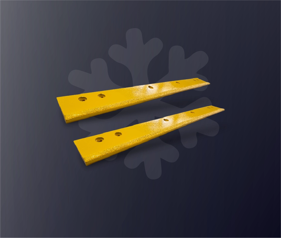
- Blade and lip edges that round: a carbide-edged or rod-protected edge, because the failure is loss of profile rather than loss of area.
- Moldboard and plow faces behind the edge: tile in a pattern, sized to the abrasion of the material and the impact the machine delivers.
- Chutes, hoppers and transfer points: tile or a composite layer, selected on coverage and thickness against the wear rate of the material handled.
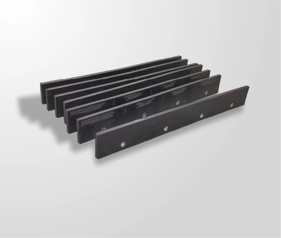
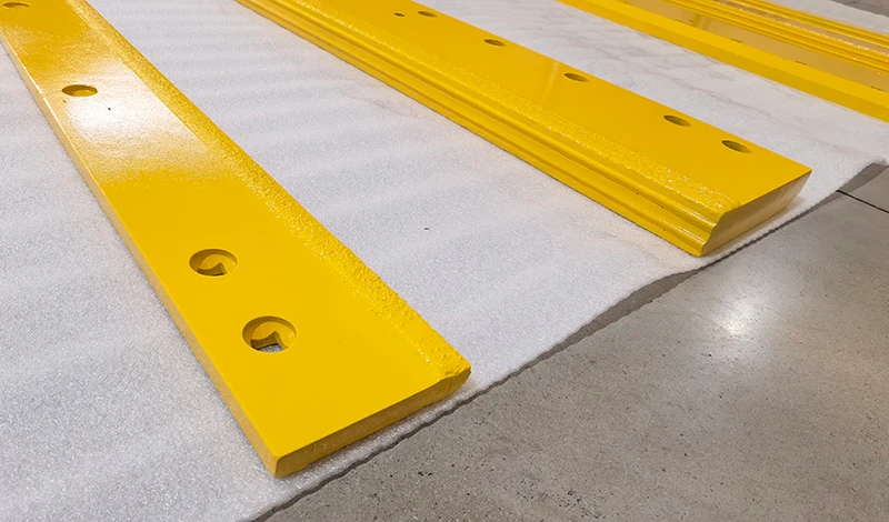
- Bucket lips and wear strips: bolt-on protection where the part has to be renewed in the field, accepting the fastener detail as part of the design.
- Thin or highly loaded sections: the lightest form that covers the zone, because a process that heats the component can weaken what it protects.
Two habits make the rule work in practice. Record where each protected component wore, including the position on the machine and the material being handled, and keep the replacement in the same form unless the record says otherwise. And where a component carries both an edge and a face, treat them as separate zones with separate solutions rather than as one part with one specification. Other wear-part categories beyond cutting edges and plow blades are collected in the wear parts beyond plows overview.
Tile, rod and composite overlay are not competing grades of the same product. Tile protects an area, rod restores an edge, and a composite layer covers ground where weight or access makes tile impractical. Coverage and thickness set the wear allowance; the fixing method sets what the component underneath can tolerate; and the failure modes are all about boundaries, whether a lifted tile edge, a spalled coating or the unprotected steel between pieces. Selecting by wear zone, and recording where each component actually wore, produces a better answer than comparing material specifications.
Send SENTHAI the component, the wear zone and the material being handled, and the technical team will review which form of protection suits the duty and what it means for fitment and serviceability.
Frequently Asked Questions
What is the wear resistance of tungsten carbide compared with steel?
Cemented carbide resists sliding abrasion far better than steel because its hardness comes from tungsten carbide grains rather than from a heat-treated steel structure. The practical comparison is not a single ratio: it depends on the abrasive, the impact level and the way the material is attached. Carbide loses much of its advantage where impacts crack the working edge or where the bond line fails, so wear resistance should be assessed for the whole protection system rather than for the material alone.
What are the disadvantages of tungsten carbide wear protection?
Weight and brittleness relative to steel are the main ones, together with the cost of the material and of applying it. A carbide covering adds stiffness and thickness to a component and tolerates less flexing, so the substrate has to suit it. Broken or lifted pieces cannot be re-formed in the field, and a repair is a workshop operation. Adhesive or braze joints also set a limit, because the attachment can fail before the carbide itself wears out.
How long will tungsten carbide wear protection last?
Long enough to be measured in wear removed rather than in a fixed period, which is why the honest answer is that life depends on the material handled, the impact level and the thickness specified. Protection should be renewed on inspection rather than on a calendar, and the useful planning input is the thickness left in the zone that wears fastest. Recording that measurement for each component quickly produces a replacement interval based on the duty rather than on a general figure.
Can wear protection be fitted to a component already in service?
Yes, provided the component has enough remaining section and the surface can be prepared properly. The wear zone is mapped on the used part rather than on the drawing, the substrate is cleaned and repaired as needed, and the covering is applied to the area that has actually worn. Where the part is too thin or already distorted, replacement is usually the more economical route. Any agreed quantity, delivery arrangement or documentation is stated in the written quotation or order documents.
Related articles
 How Sintered Carbide Wear Parts Are Made: Powder to Finished PartCarbide grades, metallurgy and joining technology
 Welding Versus Brazing Carbide: Heat Input and Cracking RiskCarbide grades, metallurgy and joining technology
 Inspecting a Braze Joint: Shear, Dye Penetrant and Visual CriteriaCarbide grades, metallurgy and joining technologyCarbide Hardness and Strength: HRA, HV and Transverse RuptureCarbide grades, metallurgy and joining technology