
Induction Brazing of Carbide: Bond Strength and Process Control
When an insert leaves a blade on the second shift, the carbide is usually not the part that failed. The joint did, and it failed because a brazing cycle is a heat treatment as…

When an insert leaves a blade on the second shift, the carbide is usually not the part that failed. The joint did, and it failed because a brazing cycle is a heat treatment as much as it is a joining operation: temperature, time, atmosphere and cooling rate all change the material either side of the bond. Induction brazing carbide gives the process the control it needs, because the heat is generated in the assembly itself and can be delivered, measured and repeated cycle after cycle.
Why the Joint Decides the Tool Life
A joint failure ends the insert’s life early.
Every carbide tip on a wear part is only as durable as the bond holding it, so a joint that loses an edge for a few seconds of heat is the limiting feature of the whole part.
The numbers behind that statement are easy to see in service. A worn insert has usually consumed its working material over weeks; a shed insert has consumed nothing and stopped the machine. Because the joint is a thin layer between two materials with different thermal expansion, it is also the region where stress concentrates, so it is the first place an incomplete bond, a void or an overheated zone produces a failure.
Two mechanisms account for most joint failures. The first is incomplete wetting: the filler metal did not flow across the whole interface, so the load is carried by the area that did bond, and the effective joint area is smaller than the drawing suggests. The second is thermal damage: excessive temperature or time at temperature degrades the binder in the carbide, weakens the steel, or leaves residual stress that cracks the insert long after it has cooled. Both are process problems, both are detectable, and both are invisible in a finished part unless someone looks for them.
Filler Metals and Wetting Behaviour
A braze is only as good as the filler metal’s ability to wet both surfaces. On carbide and steel that means a filler selected for the working temperature of the assembly, for the carbide grade it has to bond to, and for the service conditions the joint will see.
Wetting is a surface condition before it is a material property. Both surfaces have to be clean and free of oxide, oil and loose particles, and the filler has to displace whatever remains as it flows. Where a part is machined and brazed in the same shop, the cleaning sequence and the time between cleaning and brazing can be controlled; where parts sit in storage, an oxide layer forms and the joint suffers without any change in the filler metal used.
Filler metal form matters too. Preforms, wire and paste deliver different quantities to the interface, and the form has to match the joint geometry to avoid a starved or over-thick bond line. The technical fundamentals of the process, including the temperatures and filler families involved, are set out in the TWI brazing explainer, and filler metal data for specific alloys is published by suppliers such as Lucas Milhaupt. On a production line the practical control is to hold filler, cleaning and joint preparation constant, and to verify the result on a sectioned sample rather than by appearance. The preparation side of the joint, and what it does to bond strength, is covered in the surface preparation and bond strength article.
Heat Input and Thermal Cycling Control
Heat input is the variable that separates a joint that survives the season from one that fails in the first week. In induction brazing, an alternating magnetic field generates heat inside the conductive parts of the assembly, which means the heat is produced where it is needed rather than being conducted in from outside.
That advantage has to be used deliberately. Heating too quickly creates a large temperature difference between the steel body and the carbide, and the two materials expand at different rates, so the interface is loaded before the filler has even melted. Heating too slowly extends the time at temperature, which promotes grain growth in the carbide and can degrade the binder. The target is a controlled ramp to a defined brazing temperature, a short hold, and a cooling profile that does not quench the joint.
| Variable | What it controls | Consequence if wrong |
|---|---|---|
| Heating rate | Temperature difference across the joint during ramp | Thermal stress before bonding; cracked or distorted insert |
| Peak temperature | Filler flow and wetting | Incomplete fusion if low; binder damage if high |
| Time at temperature | Diffusion and grain growth | Coarser structure; lost hardness in the carbide |
| Atmosphere | Oxide formation during the cycle | Poor wetting and voids at the interface |
| Cooling rate | Residual stress in the assembly | Delayed cracking, often after the part enters service |
The welding and joining practice behind these settings is documented by technical societies such as the American Welding Society, and workshop safety for heating equipment and hot-work areas falls under general industry regulation such as 29 CFR 1910.
Automation and Repeatability
The reason induction suits production is repeatability. Once a cycle has been established for an assembly, it can be delivered by machine rather than by a bench hand, so the thousandth part receives the same heat history as the first.
Repeatability rests on three controls. The first is the coil and fixture: the geometry of the inductor and the way the work piece is positioned determine where the heat is generated, and a fixture that lets a part sit a millimetre out of position produces a different cycle. The second is power and time control, with the cycle recorded so that a deviation is visible. The third is automation of the filler delivery and the movement of the part through the cycle, which removes the operator-to-operator variation that bench brazing always carries.
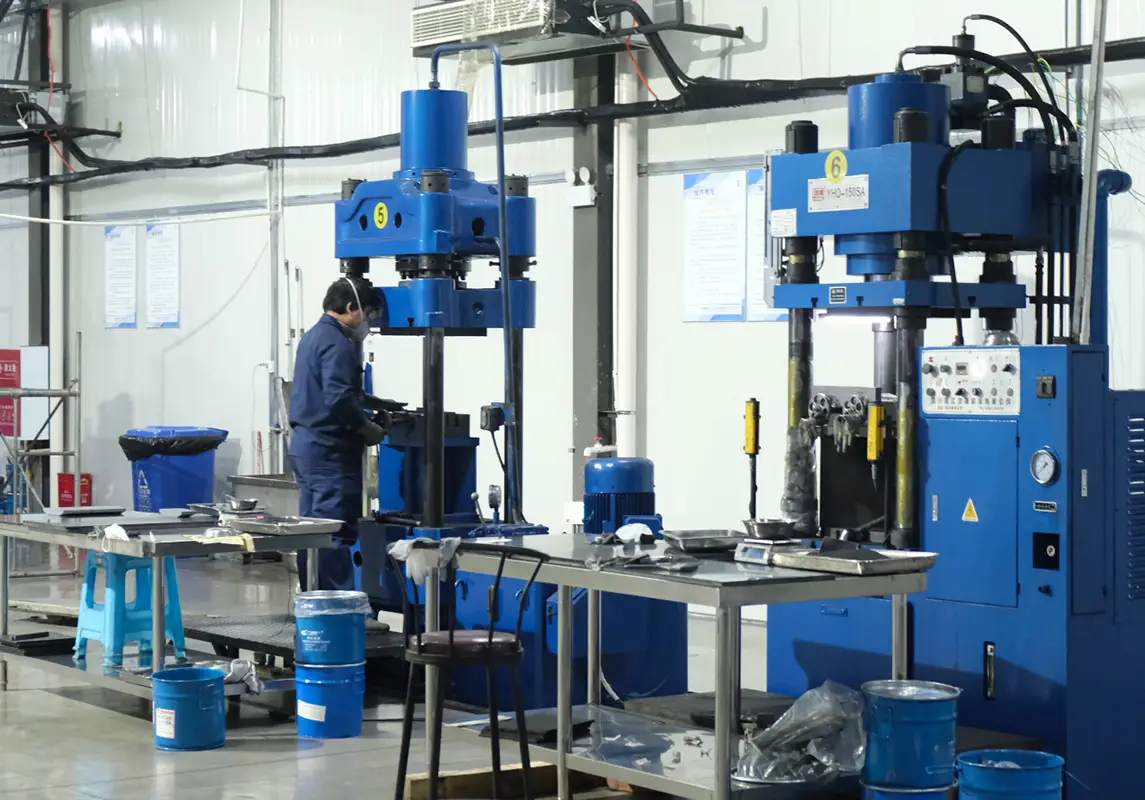
SENTHAI uses automated high-temperature induction brazing and welding with annealing in a process chain that also covers powder preparation, robotic pressing and sintering, so the joining step is controlled by the same documented production system as the parts it joins. That matters commercially as well as technically: a repeatable cycle is what allows a distributor or an OEM to order the same assembly twice and receive parts that behave the same way. The line itself is described on the factory page.
How a Joint Is Verified
By shear testing, sectioning and in-process checks.
Verification combines a destructive check on samples, a cross-section that shows the bond line, and in-process records that show every part was heated to the specified cycle.
The direct test is shear: a sample assembly is loaded until the bond fails, and the result shows whether the joint area and the filler are doing what the design assumed. Because it destroys the part, it is applied to samples produced to the same cycle rather than to production items. A sectioned and polished joint complements it, showing bond line thickness, voids, incomplete fusion and any thermal damage in the carbide beside the bond line.
Non-destructive checks cover the whole batch: a visual inspection of filler fillet formation and any discoloration that indicates overheating, plus the process record itself. Where a dye penetrant or similar method is used, its value is to detect surface-breaking discontinuities rather than internal voids. The supporting test methods for materials and joints are published by bodies such as ASTM, and the metallurgical interpretation of a joint section is covered in materials references such as those published by ASM International.
Inspection becomes meaningful when it is tied to a batch. Lot-level traceability with archived inspection results means a joint failure returns to a specific production record, where the cycle data can be checked against the specification. A more detailed account of the same production step on plow edges is given in the automated brazing article.
Where the Process Reaches Its Limits
Size, mass and geometry set the limits.
Induction works well on assemblies where the heat can be concentrated at the joint, and reaches its limits when a large mass or a complex shape makes that control difficult.
Three situations are worth recognising. The first is a heavy steel body, which acts as a heat sink and demands more power and longer cycles, increasing the risk of thermal damage to the carbide. The second is a joint that is difficult to access with a coil, where the field cannot be positioned accurately and the heating becomes uneven. The third is a very thin section behind the insert, where the temperature gradient across a small distance is steep and distortion follows.
Where these limits are reached, the practical responses are design responses: change the joint geometry so it can be heated evenly, change the assembly so a lighter section carries the load, or move to a different retention method. What does not work is forcing the cycle: increasing power to reach temperature faster usually trades a process problem for a material problem, and the failure then appears in service rather than at the bench.
What to Ask About the Brazing Line
Ask how the cycle is measured and recorded.
The answers that matter concern the cycle, the fixture, the verification and the record, because those four determine whether a joint is repeatable or incidental.
- Cycle: how are heating rate, peak temperature, hold time and cooling set and monitored for each assembly?
- Fixture and coil: how is the work piece positioned, and how is the positioning checked over a shift?
- Filler and preparation: which filler is used, and how are surface condition and time between cleaning and brazing controlled?
- Verification: how often are samples shear tested, and is a cross-section retained for the batch?
- Traceability: can a delivered assembly be tied to the cycle record for its batch?
- Documentation: what joint specification and record are supplied with an order?
The material side of the equation — which grades tolerate a brazing cycle and which are selected for it — is covered in the carbide grades reference, and grade data from materials producers such as Hyperion Materials & Technologies is a useful cross-check on the temperatures a grade will accept. A supplier that can answer all six questions is controlling a process; one that answers only the first is describing an outcome.
Induction brazing carbide is a heat treatment applied through a joining operation, and the joint it produces is normally the part that decides when an insert has to be replaced. Filler metal and surface condition determine whether the bond is complete; heating rate, peak temperature, hold time and cooling determine whether the material either side of it survives; automation and recording determine whether the next thousand assemblies behave the same way. Verification by shear test, cross-section and process record is what turns those variables into a specification that can be ordered, inspected and claimed against.
Send SENTHAI the assembly drawing, the carbide grade and the duty the part sees, and the technical team will review the joint design, the brazing cycle and the inspection record that suits the application.
Frequently Asked Questions
What is the procedure for induction brazing a carbide assembly?
The surfaces are cleaned and prepared, filler metal is placed at the joint, the assembly is positioned in an induction coil, and the field heats the steel until the filler flows and wets both surfaces. The cycle then holds briefly and cools under control so the joint does not quench. The specific heating rate, peak temperature, hold and cooling are set for the assembly and are recorded for each batch, because a generic cycle rarely suits a different joint geometry or mass.
Can induction brazing damage the carbide itself?
It can, if the cycle is not matched to the grade. Excessive peak temperature or time at temperature promotes grain growth and can degrade the binder, reducing the hardness the grade was selected for, and rapid cooling after brazing leaves residual stress that may crack the insert later. A grade intended for a brazed assembly is selected with the joining cycle in mind, and the cycle is verified on samples before a production run.
How strong is a brazed carbide joint compared with a mechanically retained insert?
The two are designed for different duties rather than ranked on strength alone. A brazed joint distributes load over the full pocket area and holds the insert rigidly, but it is not intended to be serviced in the field. A mechanically retained insert can be replaced on site and tolerates more movement, at the cost of a less rigid interface. Which is appropriate depends on the load path, the access available for maintenance and how the part is expected to fail.
What documentation should accompany a brazed assembly order?
The assembly specification, the carbide grade and the joint requirements, and a batch identification linking the delivery to the production record for that batch. Which inspection records are supplied as standard, and any additional sampling or test report agreed for a programme, is stated in the written quotation or order documents. Where a failure claim might later be needed, the record set is agreed before the order is placed wherever possible.
{
“@context”: “https://schema.org”,
“@type”: “FAQPage”,
“mainEntity”: [
{
“@type”: “Question”,
“name”: “What is the procedure for induction brazing a carbide assembly?”,
“acceptedAnswer”: {
“@type”: “Answer”,
“text”: “The surfaces are cleaned and prepared, filler metal is placed at the joint, the assembly is positioned in an induction coil, and the field heats the steel until the filler flows and wets both surfaces. The cycle then holds briefly and cools under control so the joint does not quench. The specific heating rate, peak temperature, hold and cooling are set for the assembly and are recorded for each batch, because a generic cycle rarely suits a different joint geometry or mass.”
}
},
{
“@type”: “Question”,
“name”: “Can induction brazing damage the carbide itself?”,
“acceptedAnswer”: {
“@type”: “Answer”,
“text”: “It can, if the cycle is not matched to the grade. Excessive peak temperature or time at temperature promotes grain growth and can degrade the binder, reducing the hardness the grade was selected for, and rapid cooling after brazing leaves residual stress that may crack the insert later. A grade intended for a brazed assembly is selected with the joining cycle in mind, and the cycle is verified on samples before a production run.”
}
},
{
“@type”: “Question”,
“name”: “How strong is a brazed carbide joint compared with a mechanically retained insert?”,
“acceptedAnswer”: {
“@type”: “Answer”,
“text”: “The two are designed for different duties rather than ranked on strength alone. A brazed joint distributes load over the full pocket area and holds the insert rigidly, but it is not intended to be serviced in the field. A mechanically retained insert can be replaced on site and tolerates more movement, at the cost of a less rigid interface. Which is appropriate depends on the load path, the access available for maintenance and how the part is expected to fail.”
}
},
{
“@type”: “Question”,
“name”: “What documentation should accompany a brazed assembly order?”,
“acceptedAnswer”: {
“@type”: “Answer”,
“text”: “The assembly specification, the carbide grade and the joint requirements, and a batch identification linking the delivery to the production record for that batch. Which inspection records are supplied as standard, and any additional sampling or test report agreed for a programme, is stated in the written quotation or order documents. Where a failure claim might later be needed, the record set is agreed before the order is placed wherever possible.”
}
}
]
}
Related articles
 Forestry Mulcher Teeth: Grade, Holder Type and Cost Per AcreForestry, agriculture and specialty wear parts
 VSI Crusher Wear Parts: Tips, Shoes and Distributor PlatesMining, aggregate and crusher wear parts
 Cutting Edge Steel Grades: 1045, 1080, A36 and Through-HardenedScraper, dozer and earthmoving cutting edgesScraper Blade Cutting Edges: Bowl, Elevator and Router BitsScraper, dozer and earthmoving cutting edges