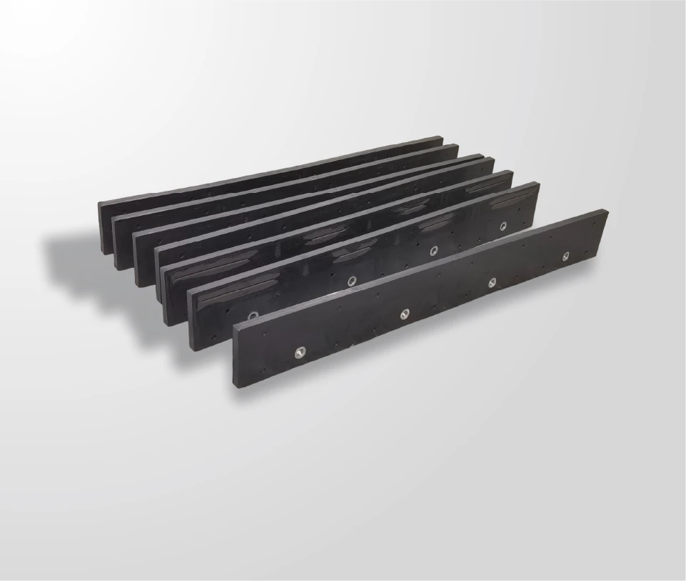
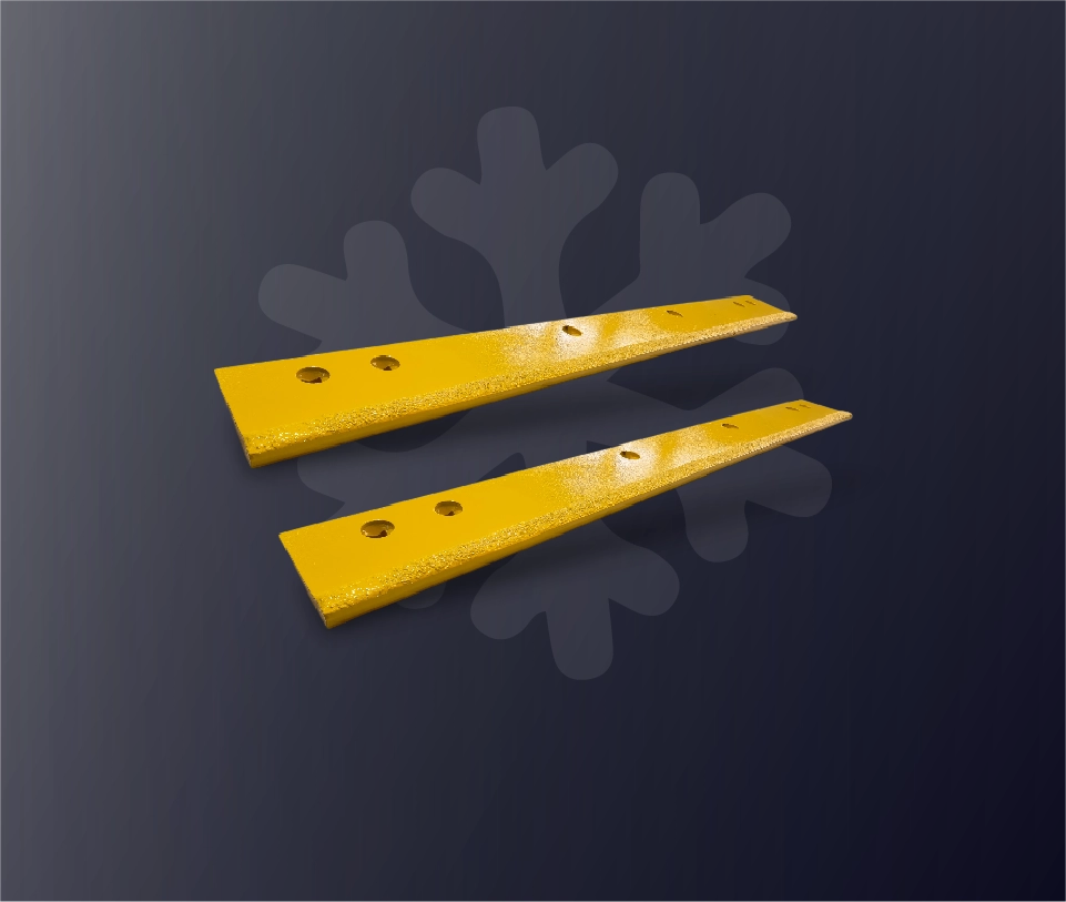
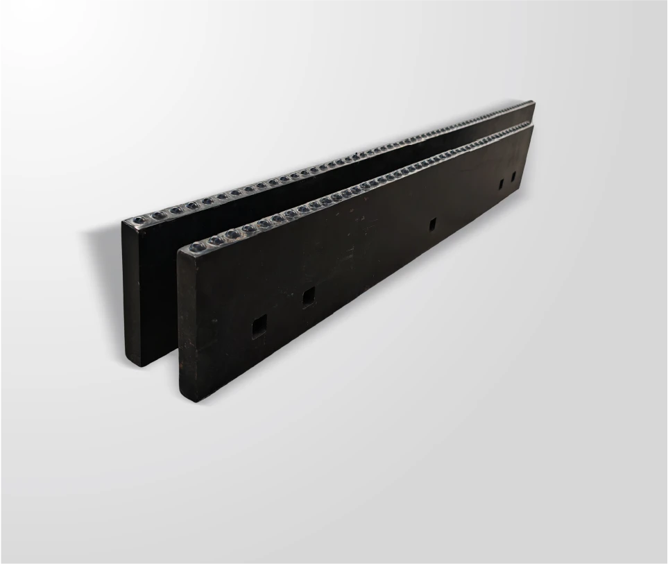
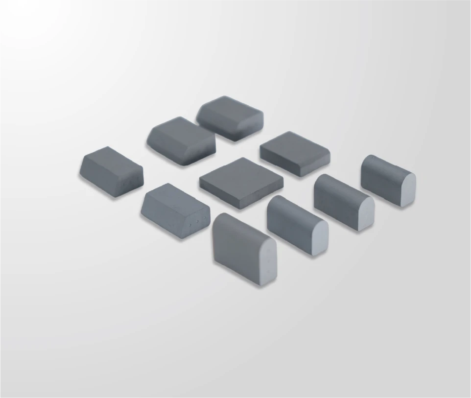
For reliable carbide brazing from Chinese factories, demand destructive pull tests to measure bond strength and X-ray inspection to verify internal void-free joint integrity. These non-negotiable QC protocols, alongside visual and dimensional checks, are your primary safeguards against substandard tools and premature field failures.
What are the critical quality control protocols for carbide brazing in a factory setting?
A robust QC protocol for carbide brazing integrates sequential inspections before, during, and after the brazing process. It begins with raw material certification and fixture alignment, proceeds to real-time process parameter monitoring, and culminates in post-braze destructive and non-destructive testing to validate the joint’s structural and mechanical integrity.
Effective quality control for carbide brazing is a multi-stage defense system, not a single checkpoint. It starts with verifying the carbide grade and steel body composition, as mismatched thermal expansion coefficients are a primary cause of cracking. During brazing, critical process parameters like furnace temperature profile, atmosphere purity, and brazing alloy flow must be continuously logged and controlled. After brazing, the real validation begins. A comprehensive protocol might include visual inspection under magnification for filler metal fillet and coverage, followed by hardness testing on the steel body to ensure the heat treatment wasn’t compromised. The crown jewels of this protocol, however, are the destructive pull tests and non-destructive X-ray inspections. These final tests provide irrefutable data on bond strength and internal soundness. Without this layered approach, you are essentially approving parts based on hope rather than evidence. How can you be sure the bond will hold under impact if you never test it to destruction? What hidden flaws might be lurking beneath a perfect-looking surface?
How does a destructive pull test verify the strength of a carbide braze joint?
A destructive pull test quantifies the tensile strength of the braze joint by applying a controlled, increasing force perpendicular to the bond line until failure occurs. The measured force at failure, divided by the bonded area, provides the ultimate tensile strength in MPa or psi, offering direct, empirical evidence of the joint’s mechanical reliability.
The pull test is the ultimate arbiter of a braze joint’s mechanical integrity, providing a pass/fail metric based on a minimum strength threshold, typically ranging from300 to over450 MPa depending on the application. The test involves fixturing the steel body of the tool and using a specialized hydraulic or mechanical pull tester to apply a purely tensile load directly to the carbide tip. The key is ensuring the force is applied perfectly perpendicular to avoid introducing shear stresses, which would skew the results. As the force increases, the joint will ultimately fail in one of three modes: within the brazing filler metal itself, at the interface between the filler and the carbide, or at the interface with the steel. The failure mode is as informative as the strength value; a cohesive failure within the filler metal often indicates excellent wetting and a bond stronger than the alloy itself. For a manufacturer like SENTHAI, running statistical process control on pull test data from each production batch is standard practice. This data doesn’t just screen bad parts; it validates that the entire brazing process—from cleaning to heating cycle—is in control. Would you trust a parachute that was never tested? Similarly, a carbide tool destined for punishing impact loads must prove its bond can withstand the forces it’s designed to encounter.
What internal defects can X-ray inspection detect in a brazed carbide assembly?
X-ray inspection, or radiography, reveals sub-surface flaws invisible to the eye. It primarily detects voids or porosity within the braze layer, incomplete filler metal flow, cracks propagating from the carbide edge, and misalignment or gaps between the carbide insert and the steel pocket, all of which critically compromise the tool’s durability and performance.
Think of X-ray inspection as a medical CT scan for your tool. It uses penetrating radiation to create a shadow image where denser materials (like tungsten carbide) appear lighter, and less dense areas (like air gaps or voids) appear darker. This allows inspectors to peer directly into the heart of the braze joint. The most common and detrimental defect is porosity—clusters of tiny gas bubbles trapped during solidification. These act as stress concentrators, initiating cracks under cyclic loading. Larger voids indicate severe flow issues or contamination. X-rays can also detect lack-of-fill, where the brazing alloy failed to wick into the entire joint interface, creating an unbonded area. Furthermore, it can reveal thermal cracks in the carbide that may have initiated during the rapid cooling phase. Modern digital X-ray systems enable detailed analysis with software that can measure void percentages against accepted standards, such as those outlined in AWS C3.7. For high-impact applications like SENTHAI’s snow plow blades, where a hidden void could lead to catastrophic tip loss, this non-destructive check is indispensable. What unseen weakness could cause a $500 blade to fail on a $50,000 plow run? X-ray inspection provides the answer before the tool ever leaves the factory, ensuring only sound parts proceed to shipment.
Which other non-destructive tests complement pull tests and X-rays for a complete QC picture?
A comprehensive QC suite includes visual inspection under high magnification, dye penetrant testing for surface cracks, and ultrasonic testing for bond integrity. These methods, combined with dimensional verification and hardness testing on the steel body, create a holistic quality assessment that covers surface, subsurface, and material property conformance.
While pull tests and X-rays are powerful, they are part of a broader toolkit. Visual inspection using a10x magnifying glass or stereo microscope is the first and most frequent check, assessing filler metal fillet consistency, surface oxidation, and obvious cracks. Dye penetrant inspection is excellent for finding hairline surface cracks on the carbide or at the braze line that might be missed visually; a colored dye is applied, drawn into defects by capillary action, and then revealed with a developer. Ultrasonic testing uses high-frequency sound waves to detect disbonds or delaminations at the interface by analyzing reflected signals. Dimensional checks with precision gauges ensure the carbide tip is correctly positioned and the tool meets print specifications, as misalignment affects performance and wear patterns. Finally, Rockwell hardness testing on the steel shank confirms the brazing thermal cycle did not anneal the steel, preserving its necessary toughness. Implementing this multi-faceted approach is what separates basic suppliers from quality-focused manufacturers. It transforms quality control from a simple gatekeeping function into a continuous feedback loop for process improvement. After all, if you only check for one type of failure, aren’t you implicitly accepting all the others?
What are the key specifications and acceptance criteria to define in a quality agreement with your manufacturer?
A definitive quality agreement must specify minimum pull test strength values, maximum allowable void percentage from X-ray analysis, visual inspection standards for fillet and surface finish, dimensional tolerances, and sampling plan frequency (e.g., AQL levels). It should also define non-conformance procedures, certification requirements, and the protocol for process change notifications.
Ambiguity in quality requirements is the root cause of most buyer-supplier disputes. A precise quality agreement acts as an objective contract, eliminating “it looks okay” subjectivity. For pull tests, you must specify the minimum MPa or psi value and the sampling rate—for instance, one destruct test per50 pieces or per furnace batch. For X-rays, define the acceptable void percentage per a recognized standard (e.g., “less than5% total void area per joint as per AWS C3.7 Class A”) and whether100% inspection or lot sampling is required. Visual criteria should reference industry standards or include annotated photos showing acceptable and rejectable fillet profiles. Crucially, the agreement must outline the sampling plan, such as an AQL (Acceptable Quality Level) of1.0 for major defects, which statistically determines how many pieces to inspect from a lot and the maximum allowable defects. It should also mandate material certifications for both carbide inserts and steel, and require notification before any change in brazing alloy supplier or furnace parameters. This document aligns expectations and provides clear grounds for rejection. Without it, you are relying on the manufacturer’s internal standards, which may not match your application’s rigors. Is your supplier’s “good enough” the same as your “mission-critical”? A detailed quality agreement ensures you are both speaking the same technical language.
| Inspection Method | Primary Defects Detected | Acceptance Criteria Example | Typical Sampling Frequency | Required Equipment |
|---|---|---|---|---|
| Destructive Pull Test | Insufficient bond strength, poor wetting | Minimum400 MPa tensile strength | Per furnace batch /1 per50 pcs | Hydraulic/Mechanical Pull Tester |
| X-Ray (Radiography) | Internal voids, porosity, cracks, lack-of-fill | 100% for critical tools / AQL sampling | Digital X-Ray Imaging System | |
| Dye Penetrant Inspection | Surface-breaking cracks on carbide or braze line | No linear indications >1.5mm allowed | 100% or AQL for visual defects | Penetrant, Cleaner, Developer |
| Ultrasonic Testing | Disbonds, delaminations at interface | Full interface bond with no disbond echoes | Often used for audit or failure analysis | Ultrasonic Flaw Detector |
How can you effectively audit a Chinese factory’s carbide brazing QC process remotely?
Effective remote auditing relies on documented evidence, live video demonstrations, and trusted third-party verification. Key steps include reviewing certified test reports with traceable serial numbers, conducting live video calls to witness pull tests or X-ray operations on your samples, and verifying calibration records for all testing equipment to ensure data integrity.
Remote auditing requires a shift from observing the factory floor to meticulously scrutinizing its data output. Start by requesting and verifying the factory’s internal quality control plan and work instructions. Then, insist on receiving digital copies of all inspection reports—pull test graphs, X-ray images with measurement annotations, and dimensional check sheets—for your specific order lots, with each report linked to a heat or batch number. During a scheduled live video audit, ask the quality manager to randomly select parts from inventory and perform a pull test or X-ray scan while you watch, ensuring the process matches their documented procedure. Pay close attention to equipment calibration stickers and dates; uncalibrated machines render all data useless. You can also send pre-marked samples to the factory for processing and testing, then have the tested samples returned to you for independent verification at a third-party lab. This approach, often employed by partners of SENTHAI, creates a closed-loop verification. It builds trust through transparency and objective evidence rather than a physical tour. If a factory is reluctant to share real-time data or calibration records, it’s a significant red flag. How can you manage what you cannot measure? And if you cannot audit the measurement process itself, how can you trust the numbers you receive?
| Factory Audit Focus Area | What to Request / Verify | Red Flags to Watch For | Pro-Tip for Remote Validation |
|---|---|---|---|
| Process Control Documentation | Furnace temperature charts, brazing alloy certs, SOPs for cleaning & fixturing | No documented parameters, handwritten logs with gaps, no revision control | Ask for a week’s worth of continuous furnace chart records for review |
| Testing Equipment & Calibration | Calibration certificates for pull testers, X-ray units, and hardness testers | Expired calibration, generic certificates not tied to specific machine serial numbers | Request a video pan of the equipment showing the serial number and calibration sticker |
| Personnel Competency | Training records for brazing operators and QC inspectors | High turnover noted, no formal training program for critical roles | During a video call, ask the QC manager to explain a reject decision from an X-ray image |
| Data Traceability & Reporting | Inspection reports that link test results to a specific production batch and PO number | Reports lack timestamps, part IDs, or are generic templates not filled with specific data | Provide a dummy PO number and ask for a sample report to see their data capture system |
Expert Views
The most critical yet often overlooked aspect of carbide brazing quality is thermal management. It’s not just about reaching the brazing temperature; it’s the entire thermal profile—the controlled ramp-up, precise soak, and, most importantly, the controlled cooldown rate. Rapid cooling induces severe thermal stress between the carbide and steel, which is the primary driver of micro-cracking and residual stress that manifests as failure in the field. A factory that masters and meticulously documents its thermal cycles for different tool geometries and material combinations demonstrates a level of process expertise that directly translates to field reliability. This deep process understanding is what separates a part that passes a one-time pull test from a tool that survives thousands of impact cycles.
Why Choose SENTHAI
Selecting a manufacturing partner goes beyond checking boxes on a QC list; it’s about choosing a partner with ingrained quality discipline. SENTHAI’s approach is rooted in vertical integration and process ownership. By controlling the entire production chain—from sintering its own carbide blanks to final brazing and testing—in its Rayong, Thailand facility, SENTHAI eliminates the variability and communication gaps common in outsourced sub-assemblies. This control allows for seamless traceability and rapid root-cause analysis if any process deviation occurs. Their investment in automated brazing lines and advanced inspection technology like digital radiography is paired with a culture that empowers QC personnel to halt production for any parameter drift. This combination of technology, process control, and organizational commitment ensures that every carbide wear part, from a standard insert to a complex plow blade, is built to deliver consistent performance in the most demanding applications.
How to Start
Initiating a successful partnership for quality carbide brazing begins with clarity and collaboration. First, clearly define your technical requirements and performance expectations in a detailed specification document, including the key QC criteria discussed. Second, engage in a technical review with potential manufacturers like SENTHAI; this is not a sales call but a deep dive into their process controls, testing capabilities, and how they would address your specific application challenges. Third, start with a pilot order. This initial batch is your live audit. Subject these samples to your own or a third-party lab’s rigorous testing, mirroring the QC you expect from the factory. Finally, based on the pilot results, co-develop a formal quality agreement that locks in the inspection protocols, acceptance criteria, and communication channels. This structured, evidence-based start builds a foundation for a transparent and reliable supply relationship.
FAQs
For high-impact applications like snow plow blades, the minimum acceptable tensile strength typically ranges from350 to450 MPa (50,000 to65,000 psi). The exact threshold depends on the carbide grade, steel body hardness, and specific blade design. Manufacturers like SENTHAI often target the higher end of this range and provide certified test reports verifying each batch meets this specification.
Yes, it is possible. A pull test is a static tensile test, while field failure often involves dynamic impact, fatigue, and thermal cycling. A joint might have adequate tensile strength but contain undetected micro-cracks or high residual stress from poor thermal management, leading to fatigue failure over time. This is why a combination of tests, including X-ray for internal soundness, is crucial.
Calibration frequency should follow the equipment manufacturer’s guidelines and international standards, typically annually. However, for high-volume production, interim checks with certified reference weights or calibration blocks may be performed monthly or quarterly. Always request to see valid, dated calibration certificates for all critical measuring and testing equipment, as this is fundamental to trusting any data provided.
A void appears as a dark spot or area on an X-ray image and represents a pocket of gas or empty space trapped within the solidified brazing filler metal. These voids reduce the effective bonded area, creating localized stress concentrations. Under load, cracks can initiate and propagate from these points, significantly reducing the joint’s fatigue life and overall durability.
Yes, several standards provide guidelines. The American Welding Society (AWS) C3.7 specification for brazing carbide tips is a key reference, classifying joints and defining acceptable void percentages. ISO17635 and ISO17636 cover non-destructive testing principles for welds and brazes, which are often applied. A reputable manufacturer will base their internal QC procedures on these or equivalent international standards.
Implementing rigorous quality control for carbide brazing is not an added cost but an essential investment in product reliability and total cost of ownership. The core takeaway is to move beyond trust-based relationships to evidence-based partnerships. Specify your requirements clearly, demand destructive and non-destructive proof of compliance, and verify the data through audits and pilot orders. By prioritizing pull tests, X-ray inspections, and a full suite of complementary checks, you ensure that the tools you receive are not just visually acceptable but are engineered to withstand real-world operational stresses. This disciplined approach to supplier quality management minimizes downtime, reduces long-term replacement costs, and ultimately protects your reputation in the field.