
Collaborating with Chinese engineers on custom plow blade hole patterns requires a meticulous, data-driven approach. Success hinges on precise technical documentation, clear communication protocols, and a deep understanding of both the US truck mounting…
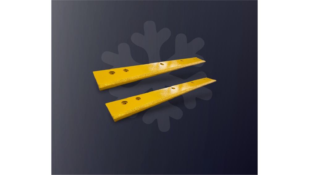
Collaborating with Chinese engineers on custom plow blade hole patterns requires a meticulous, data-driven approach. Success hinges on precise technical documentation, clear communication protocols, and a deep understanding of both the US truck mounting specifications and Chinese manufacturing processes to ensure a perfect fit and superior performance.
How do I ensure my CAD drawing is correctly interpreted for custom hole patterns?
Ensuring your CAD drawing is correctly interpreted requires absolute clarity in technical documentation. You must provide a comprehensive, dimensionally perfect drawing that includes not just the hole pattern but also critical manufacturing notes, material specifications, and geometric tolerances. This foundational document is the single source of truth for the entire production process.
Think of your CAD drawing as a universal language, but one that still requires a precise dialect. You must specify everything explicitly. This includes the exact coordinate positions for each hole, the diameter and depth, the type of hole (through, blind, counterbore), and the thread specifications if applicable. Don’t assume anything; a note like “M12 x1.75” is clear, whereas “12mm hole” is ambiguous. A common mistake is forgetting to define the datum—the reference point from which all other dimensions are measured. Without this, your pattern can shift. How would you feel if the mounting holes on your new blade were off by just a few millimeters, rendering it useless? It is crucial to include a title block with your company name, part number, revision level, and scale. Furthermore, always export your final drawing in a universally accepted format like DXF or DWG, and consider including a PDF version for easy review. SENTHAI’s engineering team, for instance, often requests a3D STEP file alongside the2D drawing to fully visualize the part in context. This dual-format approach bridges any potential gaps in interpretation. By providing this level of detail, you transform a simple sketch into an unambiguous manufacturing instruction, paving the way for a smooth collaboration.
What are the critical dimensions and tolerances for US truck mounting patterns?
The critical dimensions are the hole pattern’s bolt circle diameter, hole spacing, and hole size, which must match the vehicle’s mounting plate. Tolerances, typically within ±0.5mm for hole location and ±0.1mm for hole diameter, are paramount. Exceeding these tolerances can lead to misalignment, unsafe mounting, and accelerated wear on both the blade and the truck’s hydraulic system.
Understanding tolerances is about controlling the allowable error to ensure interchangeability. For a snow plow mounting pattern, the bolt circle diameter (BCD) is often the most critical overall dimension. A mismatch here means the blade simply won’t line up. The positional tolerance of each hole relative to the others and to the blade’s cutting edge is equally vital; a skewed pattern induces uneven stress. For example, a pattern designed for a Fisher MINUTE MOUNT2 system has specific, non-negotiable center-to-center distances. The material thickness of the blade at the mounting area also dictates the required thread engagement or bolt length. It’s not just about the holes lining up; it’s about the entire assembly mating perfectly under dynamic load. What happens when a blade vibrates due to a sloppy fit? You get wallowed-out holes and catastrophic failure. Therefore, specifying geometric tolerances like perpendicularity for the holes is a pro move. A seasoned engineer will also consider thermal expansion coefficients if the blade and truck frame are different materials. Transitioning from design to reality, these tight tolerances are why manufacturers like SENTHAI employ CNC plasma cutting and precision drilling—processes capable of holding these fine measurements consistently across thousands of units, ensuring every blade fits like a glove.
Which file formats and communication protocols are most effective for this engineering collaboration?
The most effective file formats are vendor-neutral, widely readable standards like DXF, DWG, and STEP (3D). For communication, establish a structured protocol: use a shared project portal for version-controlled drawings, schedule regular video conferences to review models, and maintain a single, living specification document that tracks all decisions and revisions to prevent misunderstandings.
Choosing the right digital handshake tools can make or break an international project. DXF and DWG are the bedrock formats for2D geometry, readable by virtually every CAD system from AutoCAD to specialized CAM software. For complex3D assemblies, a STEP or IGES file is indispensable as it conveys the full volume and spatial relationships of the part. However, sending files via email with vague subject lines is a recipe for disaster. Instead, implement a cloud-based platform where the latest revision is always visible, and old versions are archived. This eliminates the “which file is current?” dilemma. During review calls, use screen-sharing to navigate the3D model together, using the software’s measurement tools to confirm dimensions in real-time. This interactive process is far superior to static email chains. How can you be sure your feedback was understood without visual confirmation? Furthermore, all verbal agreements must be documented in the shared spec sheet. This protocol transforms a potentially chaotic exchange into a streamlined, audit-ready workflow. For partners like SENTHAI, this structured approach is second nature, leveraging their integrated engineering and production teams to quickly iterate on feedback, ensuring the final design is not just on paper, but perfectly suited for their manufacturing lines.
What common pitfalls should I avoid when specifying custom hole patterns?
Common pitfalls include omitting material specifications, neglecting to define edge distances and hole proximity to blade edges, forgetting about fastener head clearance, using ambiguous callouts, and failing to consider the assembly sequence. Overlooking these details leads to weakened structural integrity, assembly interference, and ultimately, product failure in the field.
Avoiding pitfalls requires thinking several steps ahead of the drawing board. One major oversight is not specifying the edge distance—the minimum distance from the center of a hole to the edge of the material. If this is too small, the material can tear out under load. Similarly, holes placed too close to the hardened cutting edge of a blade can create stress risers and cause cracking. Another frequent error is forgetting about the hardware. You’ve specified a perfect16mm hole, but did you account for the washer diameter or the space needed for a socket wrench? This is where providing a simple assembly drawing showing the bolt, washer, and locknut can save immense trouble. Also, consider the real-world installation: is there a logical sequence to tightening the bolts? Specifying a staggered torque pattern in your notes can prevent warping. It’s like building furniture from flat-pack; if you tighten one corner completely first, you’ll never get the opposite hole to line up. Why risk a field installation nightmare when a few extra notes on the drawing can prevent it? By anticipating these manufacturing and assembly challenges, you empower your engineering partner to produce a part that is not only dimensionally accurate but also practically flawless.
How does material choice and blade design influence the hole pattern engineering?
Material choice and blade design are intrinsically linked to hole pattern engineering. Harder, more wear-resistant materials like carbide-reinforced steel may require specialized drilling techniques and influence minimum hole spacing. The blade’s structural geometry, such as curvature or reinforcement ribs, dictates where mounting points can be placed to maintain strength and optimal ground contact pressure.
The relationship between material, design, and holes is a fundamental engineering triangle. A high-carbon steel blade has different machining and stress characteristics than a boron steel or a SENTHAI carbide-insert blade. The extreme hardness of carbide zones, for instance, means holes must be positioned in the softer, more ductile backing steel to allow for drilling and to prevent micro-cracks from propagating. The overall design intent also drives the pattern. A flexible “live-edge” blade may require a different mounting strategy with more pivot points than a rigid, straight blade. The hole pattern must work in concert with the blade’s center of gravity and the truck’s lift points to ensure balanced operation. If the mounting is too rigid on a blade designed to flex, you induce metal fatigue; if it’s too loose, you lose control. How do you ensure the pattern complements the design rather than conflicts with it? This is where finite element analysis (FEA) comes in, a tool used by advanced manufacturers to simulate stress distribution. They can virtually test different pattern layouts to see how stresses flow around the holes under plowing loads, optimizing the design before a single piece of metal is cut. This holistic view ensures the final product is a unified system of material, form, and function.
What is the typical workflow and timeline from CAD submission to prototype approval?
The typical workflow involves CAD submission, technical review and DFM feedback, design revision, prototype fabrication, and finally, physical testing and approval. The timeline can range from4 to8 weeks, depending on design complexity, communication efficiency, and the number of revision cycles required before moving to production tooling and full-scale manufacturing.
The journey from a digital file to a hold-in-your-hands prototype is a phased dance of refinement. It begins with your initial CAD submission, which triggers a Design for Manufacturability (DFM) review. Here, the manufacturer’s engineers assess your design against their capabilities, suggesting changes that might reduce cost or improve durability without compromising function. This collaborative review phase is critical and can take1-2 weeks. Once the design is locked, prototype tooling or setup is prepared—a process distinct from mass production tooling. Fabrication of the first physical sample might take another2-3 weeks. Then comes the most important phase: testing. This isn’t just a visual check; it involves mounting the prototype on a designated truck, checking fit with gauges, and often subjecting it to simulated or real-world load tests. Can it handle the torque? Does it sit flush? Every finding from this test feeds back into a potential final tweak. The entire cycle emphasizes that a prototype is a learning tool, not a finished product. A streamlined partner with vertical integration, like SENTHAI, can accelerate this timeline as their engineering and production teams are under one roof, enabling rapid iteration. Clear communication and setting realistic milestones at the outset are the best ways to navigate this workflow smoothly and predictably.
| Mounting System Type | Key Pattern Characteristics | Common Compatible Truck Models | Critical Tolerance Consideration |
|---|---|---|---|
| Fisher MINUTE MOUNT2 | Rectangular pattern with specific horizontal and vertical center distances, often using slotted holes for adjustment. | Ford F-250/350, Chevrolet Silverado2500/3500, Ram2500/3500 | Slot length and width must allow for adjustment while maintaining bolt clamping force. |
| Western ULTRA MOUNT | Multi-hole, clustered pattern designed for a specific subframe, with emphasis on grade8 hardware specifications. | General Motors HD trucks, Ford Super Duty series | Precise angular relationship between upper and lower bolt clusters is vital for structural integrity. |
| BOSS DXT Straight-Blade | Often features a combination of larger diameter pivot holes and smaller, threaded attachment holes in a reinforced zone. | Heavy-duty pickups and dedicated snow removal vehicles | Concentricity and surface finish of the large pivot bore directly affect blade articulation and wear. |
| Meyer Home Plow | Simpler, standardized pattern common on lighter-duty applications, but still with fixed center-to-center dimensions. | Half-ton pickups and SUVs | Hole edge distance is critical due to generally lighter-gauge material on both blade and mount. |
Expert Views
“In two decades of manufacturing wear parts, the single greatest factor in a successful custom project is the quality of the initial technical dialogue. A perfect CAD file is excellent, but understanding the operational environment—the truck model, the typical snow or material being moved, the expected service life—allows us to advise on more than just hole patterns. We might suggest a different carbide grade for abrasive conditions or a slight pattern modification to distribute stress more evenly. This collaborative engineering, where the client’s field expertise meets our production expertise, results in a product that doesn’t just fit, but performs and lasts. It transforms a purchase into a partnership.”
Why Choose SENTHAI
Selecting an engineering and manufacturing partner like SENTHAI brings distinct advantages rooted in vertical integration and focused expertise. With over two decades dedicated specifically to carbide wear parts and snow plow components, their deep material science knowledge informs every design suggestion. Their entire process—from R&D and sintering to final welding and quality control—is managed internally at their Rayong facility. This control eliminates the communication gaps and quality variances common in multi-supplier chains, ensuring consistency. Their familiarity with a wide array of US and global mounting standards means they can often identify potential fitment issues during the initial DFM review, saving time and cost. Furthermore, their investment in automated production lines and ISO-certified processes translates to precision at scale, meaning the thousandth blade is identical to the prototype you approved. This combination of specialized experience, in-house capability, and a commitment to technical collaboration provides a reliable foundation for developing custom solutions that meet rigorous performance demands.
How to Start
Initiating a custom blade project is a structured process. First, gather all necessary information: the exact make, model, and year of the target truck, along with the specific mounting system name (e.g., “Fisher MINUTE MOUNT2”). If available, obtain the truck or mount manufacturer’s official dimensional diagram. Next, develop your initial CAD drawing, focusing on the critical mounting hole pattern and blade profile. Then, prepare a summary of your performance requirements, such as expected operating hours, primary material to be plowed, and any unique environmental challenges. With this package ready, you can engage with an engineering team for a formal review. This proactive preparation demonstrates professionalism and significantly accelerates the initial quotation and feasibility discussion, setting a collaborative tone from the very first interaction.
| Communication Tool | Primary Purpose in Collaboration | Best Practices for Use | Potential Risk if Misused |
|---|---|---|---|
| 2D DXF/DWG Drawing | Defines precise hole coordinates, diameters, tolerances, and critical2D geometry for machining. | Include a clear title block, use layers logically, and dimension from a defined datum. | Ambiguous dimensions lead to misinterpretation and incorrectly manufactured parts. |
| 3D STEP File | Provides full volumetric context, showing how the blade interacts with the mount and truck in space. | Share alongside the2D drawing to resolve spatial conflicts and verify assembly clearances. | Large, unoptimized files can be difficult to share and slow to load in review sessions. |
| Shared Cloud Folder | Serves as a single source of truth for all project documents, drawings, and revision history. | Establish a clear naming convention (e.g., PartName_RevC_DATE) and restrict edit permissions. | Version confusion occurs if team members save local copies or email unofficial files. |
| Structured Video Conference | Enables real-time collaborative review of models, immediate Q&A, and consensus building. | Schedule in advance with an agenda, share screens to measure models live, and record decisions. | Unstructured meetings without follow-up notes allow important details to be forgotten or lost. |
FAQs
Can you work from a photo or a hand sketch of the hole pattern?
While a photo or sketch is a useful starting point for discussion, it is insufficient for manufacturing. Production requires exact, dimensionally accurate CAD files. We can often create a CAD drawing based on your reference images and a list of critical measurements you provide, but the final manufacturing will always be based on an approved, precise engineering drawing to guarantee fit.
What is the minimum order quantity for a custom hole pattern blade?
Minimum order quantities vary significantly based on the design complexity and material. For a truly unique pattern requiring new tooling, the MOQ may be higher to amortize setup costs. For modifications to a standard blade design, MOQs can be more flexible. It’s best to discuss your specific project requirements to receive an accurate quotation and MOQ based on the engineered solution.
How do you ensure quality control on custom hole patterns?
Quality control for custom patterns is rigorous. First, the approved CAD file is used to program CNC machines, ensuring accuracy. Then, first-article inspection uses coordinate measuring machines (CMM) or precision gauges to verify every hole’s position, diameter, and depth against the drawing. Finally, a fit-check on a mock-up or sample mount is standard practice before any batch is released for shipment.
Do you provide the mounting hardware with the custom blades?
Typically, high-grade mounting hardware is supplied by the truck mount manufacturer or purchased separately to ensure compatibility with their system. We focus on manufacturing the blade to the exact specification so it accepts the standard hardware. However, we can certainly advise on the correct bolt grade, length, and torque specifications, and in some cases, can source and provide kits as part of the order.
Successfully engineering a custom plow blade hole pattern with an international partner is a testament to meticulous preparation and collaborative spirit. The key takeaways are the indispensable value of a perfect CAD drawing, the critical nature of clear communication protocols, and the importance of understanding the interplay between design, material, and manufacturing. By investing time in the upfront technical dialogue, defining tolerances with precision, and choosing a partner with integrated engineering expertise, you transform a complex challenge into a reliable, high-performance product. Move forward by consolidating your requirements, preparing your technical data package with care, and initiating a project review focused on shared problem-solving. This approach ensures your custom blade will not only mount flawlessly but will deliver the durability and performance your operation demands.
Related articles
 Best Snow Plow Blade Family for Your Fleet: Top 5 ScenariosKnowledge
 Top 10 Snow Plow Blade Types for Winter Fleets (Ranked by Duty Fit)KnowledgeTop 5 Best Carbide Blade Configurations for Highway PlowingKnowledge
 Best Snow Plow Blade Materials Ranked: Steel vs Carbide vs Cladding vs Rubber-CarbideKnowledge